
This lab use part of the Arista Spine and Leaf topology I have created in GNS3. Specifically, I will only be using three switches. One spine and two leaf switches. I have chosen this to get a good understanding of the core concepts of VXLAN, HER and EVPN.
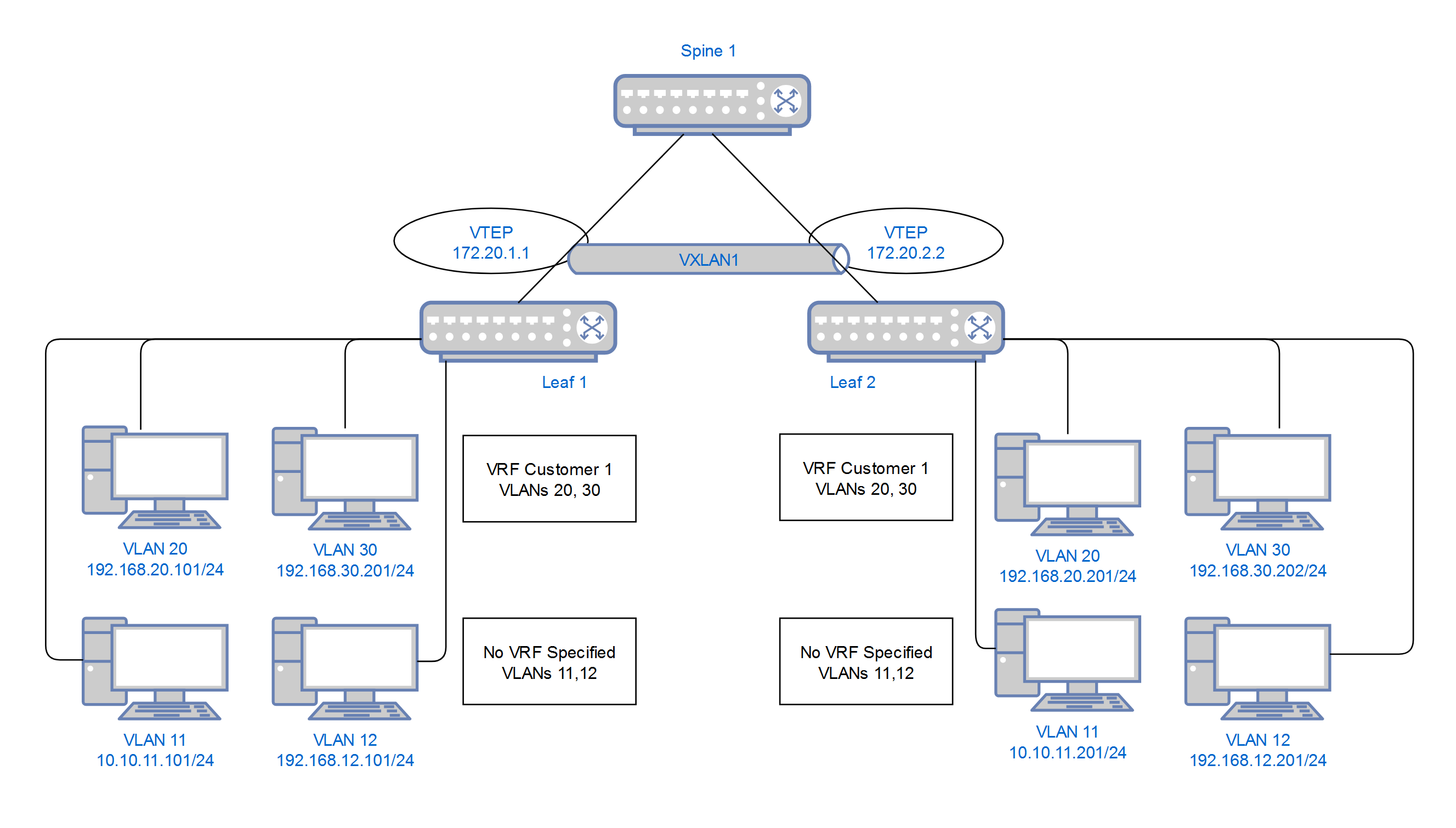
This is the basic VXLAN topology that I will use to demonstrate the VXLAN configuration and how to get the hosts to communicate. I will be using two methods;
– Head End Replication
– EVPN
Head End Replication Or EVPN?
There are differences between VXLAN Head End Replication and EVPN (Ethernet Virtual Private Network). Mainly flooding on the part of HER. I like to think of the difference between the two like multicast sparse mode and dense mode.
EVPN (Ethernet Virtual Private Network) used MAC and ARP learning that allows EVPN to provide a distributed control plane from MAC and ARP learning across the DC fabric. It allows each VTEP to only learn about the MAC addresses and ARP entries associated with specific VXLAN segments.
It avoids unnecessary flooding of BUM traffic to all VTEPs by leveraging the MAC and ARP information learned through the control plane.
This is different to how Head End Replication works which uses flood and learn behaviour. When a VTEP receives a packet with an unknown destination MAC address, it floods the packet to all other VTEPs in the overlay network. The destination VTEP then learns the location of the MAC address and installs an entry in its forwarding table. This may causes scalability issues as a topology grows larger
Configuration
For this lab I have used vEOS 4.26.2F
Device configuration will be in stages to confirm each step as we go. For the complete device configs, go here. And for individual config section, see links below.
Underlay Configuration
VTEP Configuration
VXLAN Head End Replication Layer 2
VXLAN Head End Replication Layer 3
VXLAN EVPN – No VRF
VXLAN EVPN – With VRF
VRF Route Leaking
IP Addressing Scheme
| Switch | Eth1 (eBGP UL) | Eth2 (eBGP UL) | Lo0 (BGP EVPN) | Lo1 (VTEP) | VLAN11 | VLAN12 | VLAN20 | VLAN30 |
|---|---|---|---|---|---|---|---|---|
| Spine1 | 10.1.11.0/31 | 10.1.12.0/31 | 10.10.10.1/32 | – | – | – | – | – |
| Leaf1 | 10.1.11.1/31 | 10.2.11.1/31 (Spine 2) | 10.10.10.11/32 | 172.20.1.1/32 | 10.10.11.254/24 | 192.168.12.254/24 | 192.168.20.1/24 | 192.168.30.1/24 |
| Leaf2 | 10.1.12.1/31 | 10.2.12.1/31 (Spine 2) | 10.10.10.12/32 | 172.20.2.2/32 | 10.10.11.254/24 | 192.168.12.254/24 | 192.168.20.1/24 | 192.168.30.1/24 |
Underlay
The underlay is using eBGP. There are several different designs for the underlay, which I am not going to get into here. My understanding is that eBGP is the most flexible and widest used. I have a discussed other options in a design guide.
Spine 1
|
0 1 2 3 4 5 6 7 8 9 10 11 12 13 14 15 16 17 18 19 20 21 22 23 24 25 26 27 28 29 30 31 32 33 34 |
interface Ethernet1 description LINK to LEAF1.LAB mtu 9200 logging event link-status no switchport ip address 10.1.11.0/31 arp aging timeout 1200 interface Ethernet2 description LINK to LEAF2.LAB mtu 9200 logging event link-status no switchport ip address 10.1.12.0/31 arp aging timeout 1200 !!! Check basic IP Connectivity !!! interface Loopback0 description MANAGEMENT ip address 10.10.10.1/32 router bgp 65000 router-id 10.10.10.1 distance bgp 20 200 200 neighbor LEAFS65111 peer group neighbor LEAFS65111 remote-as 65111 neighbor 10.1.11.1 peer group LEAFS65111 neighbor 10.1.11.1 description LEAF1.LAB ! neighbor LEAFS65112 peer group neighbor LEAFS65112 remote-as 65112 neighbor 10.1.12.1 peer group LEAFS65112 neighbor 10.1.12.1 description LEAF2.LAB |
Leaf 1
|
0 1 2 3 4 5 6 7 8 9 10 11 12 13 14 15 16 17 18 19 20 21 22 23 24 25 26 27 28 29 30 31 32 |
interface Ethernet1 description LINK to SPINE1.LAB mtu 9200 logging event link-status no switchport ip address 10.1.11.1/31 arp aging timeout 1200 interface Ethernet2 description LINK to SPINE2.LAB mtu 9200 logging event link-status no switchport ip address 10.2.11.1/31 arp aging timeout 1200 !!! Check basic IP Connectivity !!! interface Loopback0 description MANAGEMENT ip address 10.10.10.11/32 router bgp 65111 router-id 10.10.10.11 distance bgp 20 200 200 neighbor SPINE peer group neighbor SPINE remote-as 65000 neighbor 10.1.11.0 peer group SPINE neighbor 10.1.11.0 description SPINE1.LAB neighbor 10.2.11.0 peer group SPINE neighbor 10.2.11.0 description SPINE2.LAB redistribute connected |
Leaf 2
|
0 1 2 3 4 5 6 7 8 9 10 11 12 13 14 15 16 17 18 19 20 21 22 23 24 25 26 27 28 29 30 31 |
interface Ethernet1 description LINK to SPINE1.LAB mtu 9200 logging event link-status no switchport ip address 10.1.12.1/31 arp aging timeout 1200 interface Ethernet2 description LINK to SPINE2.LAB mtu 9200 logging event link-status no switchport ip address 10.2.12.1/31 arp aging timeout 1200 !!! Check basic IP Connectivity !!! interface Loopback0 ip address 10.10.10.12/32 router bgp 65112 router-id 10.10.10.12 distance bgp 20 200 200 neighbor SPINE peer group neighbor SPINE remote-as 65000 neighbor 10.1.12.0 peer group SPINE neighbor 10.1.12.0 description SPINE1.LAB neighbor 10.2.12.0 peer group SPINE neighbor 10.2.12.0 description SPINE2.LAB redistribute connected |
Testing Commands
|
0 1 2 3 |
sh ip bgp summary sh ip route |
VTEP
Leaf 1
|
0 1 2 3 4 5 6 7 8 |
interface Loopback1 description LOGICAL VTEP ip address 172.20.1.1/32 router bgp 65111 router-id 10.10.10.11 network 172.20.1.1/32 |
Leaf 2
|
0 1 2 3 4 5 6 7 8 |
interface Loopback1 description LOGICAL VTEP ip address 172.20.2.2/32 ! router bgp 65112 router-id 10.10.10.12 network 172.20.2.2/32 |
VXLAN Head End Replication (HER) Layer 2
There is a template to follow the VXLAN config that is below, this is specifically for HER – Head End Replication.
|
0 1 2 3 4 5 6 |
interface Vxlan1 vxlan source-interface Loopback1 vxlan udp-port 4789 vxlan vlan [VLAN-NUM] vni [VNI-NUM] vxlan vlan [VLAN-NUM] flood vtep [VTEP1ADD] [VTEP2ADD] [VTEP3ADD] |
Leaf 1
|
0 1 2 3 4 5 6 |
interface Vxlan1 vxlan source-interface Loopback1 vxlan udp-port 4789 vxlan vlan 12 vni 55512 vxlan vlan 12 flood vtep 172.20.2.2 |
Leaf 2
|
0 1 2 3 4 5 6 |
interface Vxlan1 vxlan source-interface Loopback1 vxlan udp-port 4789 vxlan vlan 12 vni 55512 vxlan vlan 12 flood vtep 172.20.1.1 |
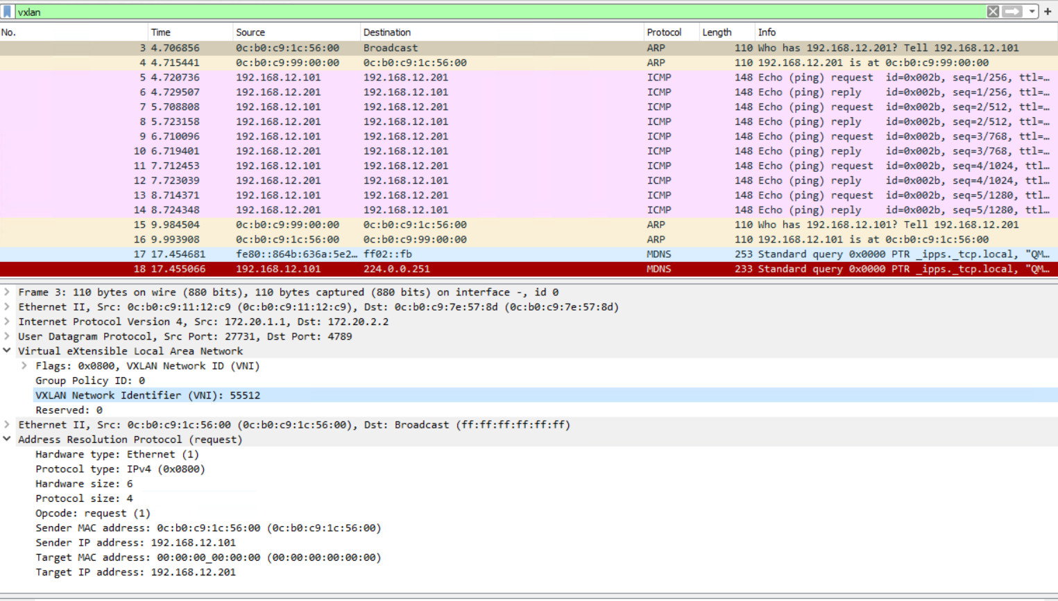
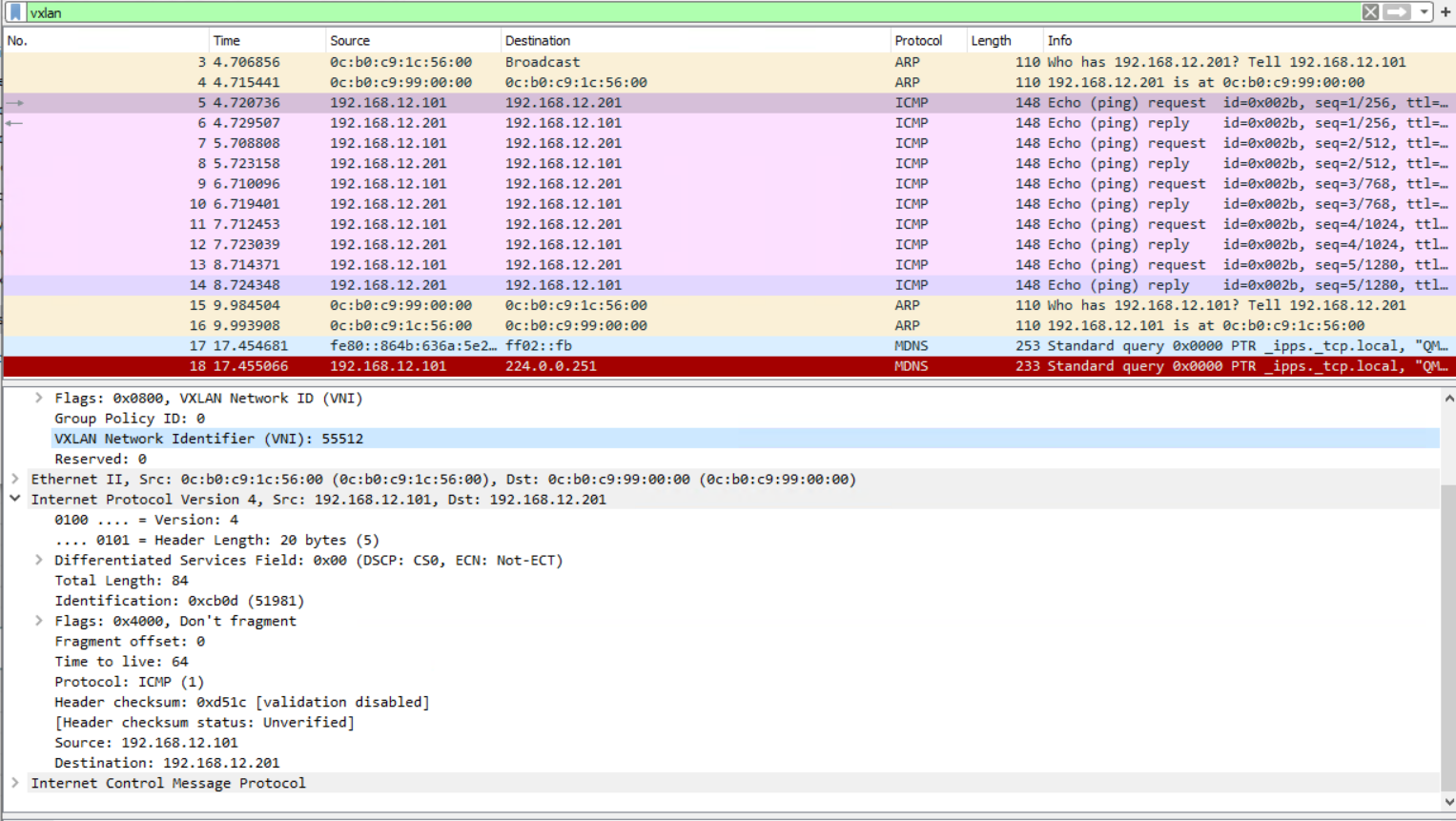
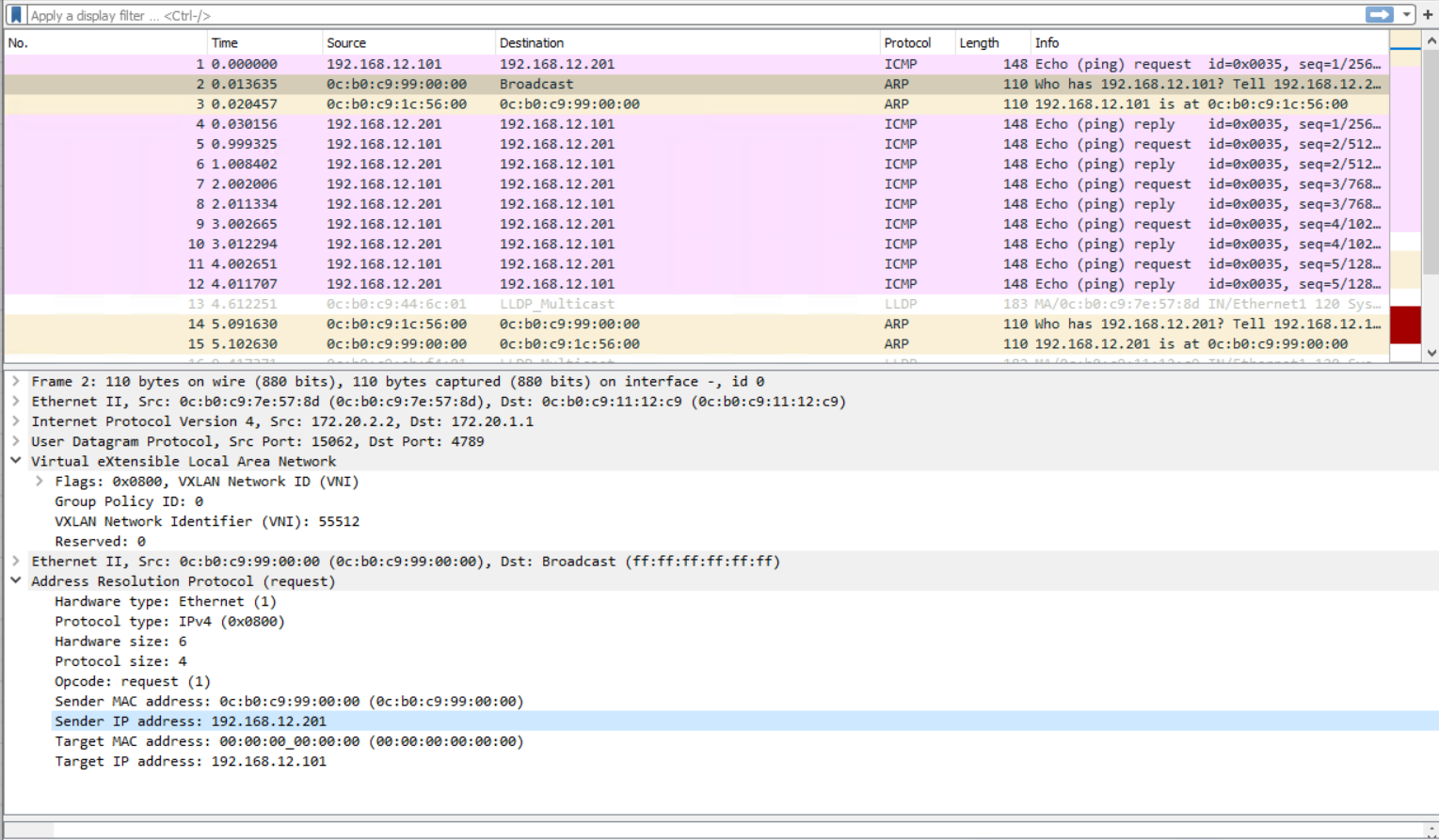
Testing
This is for VLAN 12 only and therefore is layer 2 only. No SVIs are required.
|
0 1 2 3 4 5 |
sh vlan id 12 sh run int vxlan 1 show ip int br show mac address-table vlan 12 |
|
0 1 2 3 4 5 6 7 8 9 10 |
leaf1(config-if-Vx1)#show mac address-table vlan 12 Mac Address Table ------------------------------------------------------------------ Vlan Mac Address Type Ports Moves Last Move ---- ----------- ---- ----- ----- --------- 12 0cb0.c91c.5600 DYNAMIC Et10 1 0:03:13 ago 12 0cb0.c999.0000 DYNAMIC Vx1 1 0:00:06 ago Total Mac Addresses for this criterion: 2 |
|
0 1 2 3 4 5 6 7 8 9 10 |
leaf2(config-if-Vx1)#show mac address-table vlan 12 Mac Address Table ------------------------------------------------------------------ Vlan Mac Address Type Ports Moves Last Move ---- ----------- ---- ----- ----- --------- 12 0cb0.c91c.5600 DYNAMIC Vx1 1 0:00:10 ago 12 0cb0.c999.0000 DYNAMIC Et10 1 0:00:10 ago Total Mac Addresses for this criterion: 2 |
VXLAN Head End Replication (HER) Layer 3
Leaf 1
|
0 1 2 3 4 5 6 7 8 9 10 11 12 13 14 15 16 17 18 19 20 21 22 |
vlan 11 name LEAF1VLAN ! interface Ethernet11 description PC140 switchport access vlan 11 interface Vxlan1 !vxlan source-interface Loopback1 !vxlan udp-port 4789 vxlan vlan 11 vni 10011 vxlan vlan 11 flood vtep 172.20.2.2 interface Vlan11 no autostate ip address virtual 10.10.11.254/24 interface Vlan12 no autostate ip address virtual 192.168.12.254/24 ip virtual-router mac-address 00:00:00:00:aa:aa |
Leaf 2
|
0 1 2 3 4 5 6 7 8 9 10 11 12 13 14 15 16 17 18 |
vlan 11 name LEAF1VLAN interface Vxlan1 !vxlan source-interface Loopback1 !vxlan udp-port 4789 vxlan vlan 11 vni 10011 vxlan vlan 11 flood vtep 172.20.1.1 interface Vlan11 no autostate ip address virtual 10.10.11.254/24 interface Vlan12 no autostate ip address virtual 192.168.12.254/24 ip virtual-router mac-address 00:00:00:00:aa:aa |
Testing
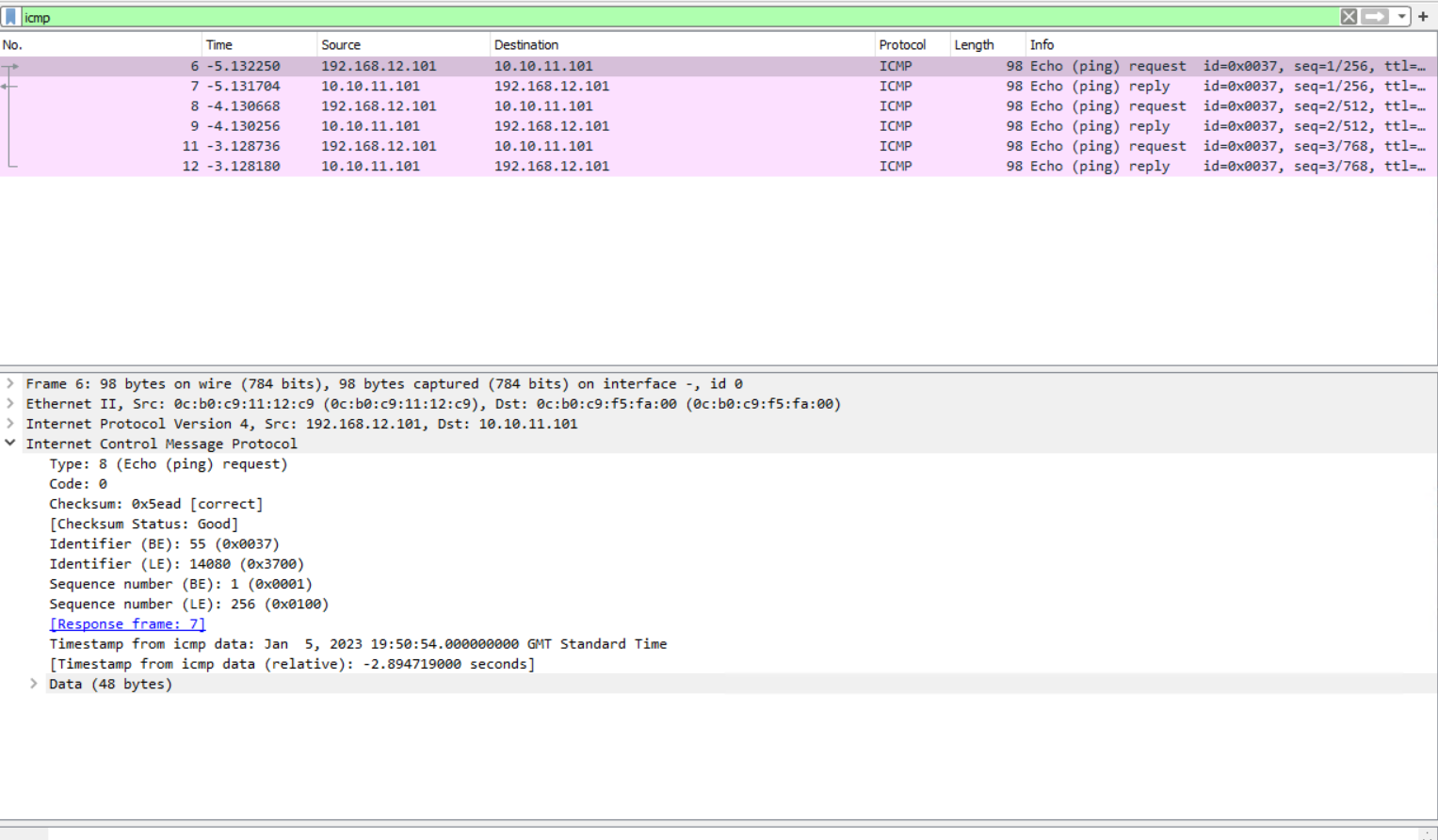
Traffic from VLAN 11 to VLAN 12 going via Spine 1 VXLAN encapsulated from Leaf 1 to Leaf 2 and also interVLAN routing on Leaf 1.
|
0 1 2 3 4 |
leaf1(config)#sh int status | i 11|12 Et10 PC110 connected 12 full 1G EbraTestPhyPort Et11 PC140 connected 11 full 1G EbraTestPhyPort |
|
0 1 2 3 |
leaf2(config)#sh int status | i 12 Et10 PC210 connected 12 full 1G EbraTestPhyPort |
|
0 1 2 3 4 5 6 7 8 |
leaf1(config-if-Vx1)#show ip arp 192.168.12.201 Address Age (sec) Hardware Addr Interface 192.168.12.201 0:02:01 0cb0.c999.0000 Vlan12, Vxlan1 leaf2(config)#show ip arp 192.168.12.201 Address Age (sec) Hardware Addr Interface 192.168.12.201 1:48:06 0cb0.c999.0000 Vlan12, Ethernet10 |
VXLAN EVPN No VRF
Any HER configuration needs to be removed on the VXLAN interface. EVPN must also be enabled using a service command.
|
0 1 2 3 |
no interface vxlan 1 service routing protocols model multi-agent |
This example creates a two VLANs 11 and 12 in the same way as HER did, but this time using EVPN. I had a few issues with this config.
– I needed to redistribute connected into Spine 1 BGP
– I did not use the command no bgp default ipv4-unicast on the leaf switches
Both of these commands would cause the BGP neighbourships to fail.
Spine 1
|
0 1 2 3 4 5 6 7 8 9 10 11 12 13 14 15 16 17 18 |
router bgp 65000 neighbor EVPN peer group neighbor EVPN next-hop-unchanged neighbor EVPN update-source Loopback0 neighbor EVPN ebgp-multihop 3 neighbor EVPN send-community extended ! neighbor 10.10.10.11 peer group EVPN neighbor 10.10.10.11 remote-as 65111 neighbor 10.10.10.11 description LEAF1 neighbor 10.10.10.12 peer group EVPN neighbor 10.10.10.12 remote-as 65112 neighbor 10.10.10.12 description LEAF2 redistribute connected address-family evpn neighbor EVPN activate |
Leaf 1
|
0 1 2 3 4 5 6 7 8 9 10 11 12 13 14 15 16 17 18 19 20 21 22 23 24 25 26 27 28 29 30 31 32 33 34 35 36 37 38 39 40 41 42 |
router bgp 65111 neighbor EVPN peer group neighbor EVPN remote-as 65000 neighbor EVPN update-source Loopback0 neighbor EVPN ebgp-multihop 3 neighbor EVPN send-community extended neighbor 10.10.10.1 peer group EVPN neighbor 10.10.10.1 description SPINE1.LAB neighbor 10.10.10.2 peer group EVPN neighbor 10.10.10.2 description SPINE2.LAB ! address-family evpn neighbor EVPN activate interface Vxlan1 vxlan source-interface Loopback1 vxlan udp-port 4789 vxlan vlan 11 vni 10011 vxlan vlan 12 vni 10012 ! router bgp 65111 vlan 11 rd 65111:10011 route-target both 11:10011 redistribute learned vlan 12 rd 65111:10012 route-target both 12:10012 redistribute learned vlan 11 vlan 12 interface Vlan11 no autostate ip address virtual 10.10.11.254/24 interface Vlan12 no autostate ip address virtual 192.168.12.254/24 |
Leaf 2
|
0 1 2 3 4 5 6 7 8 9 10 11 12 13 14 15 16 17 18 19 20 21 22 23 24 25 26 27 28 29 30 31 32 33 34 35 36 37 38 39 40 41 42 43 |
router bgp 65112 !no bgp default ipv4-unicast neighbor EVPN peer group neighbor EVPN remote-as 65000 neighbor EVPN update-source Loopback0 neighbor EVPN ebgp-multihop 3 neighbor EVPN send-community extended neighbor 10.10.10.1 peer group EVPN neighbor 10.10.10.1 description SPINE1.LAB neighbor 10.10.10.2 peer group EVPN neighbor 10.10.10.2 description SPINE2.LAB ! address-family evpn neighbor EVPN activate interface Vxlan1 vxlan source-interface Loopback1 vxlan udp-port 4789 vxlan vlan 11 vni 10011 vxlan vlan 12 vni 10012 ! router bgp 65112 vlan 11 rd 65112:10011 route-target both 11:10011 redistribute learned vlan 12 rd 65112:10012 route-target both 12:10012 redistribute learned vlan 11 vlan 12 interface Vlan11 no autostate ip address virtual 10.10.11.254/24 interface Vlan12 no autostate ip address virtual 192.168.12.254/24 |
Testing
|
0 1 2 3 4 5 |
show vxlan vtep show ip bgp summary sh bgp evpn summary show bgp evpn route-type mac-ip |
BGP EVPN Capture shows the BGP networks that are shared, as well as the fact that EVPN is being used.
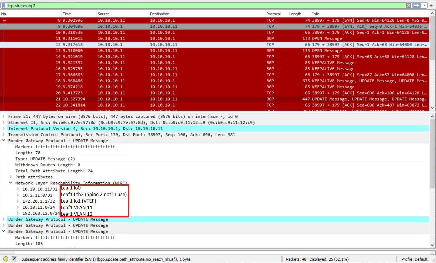
Each leaf switch has learnt the routes via BGP for the remote hosts. The hosts that are local are also listed and are denoted with “i” for their path.
|
0 1 2 3 4 5 6 7 8 9 10 11 12 13 14 15 16 17 18 19 20 21 22 23 |
leaf1(config-if-Et10)#sh bgp evpn route-type mac-ip BGP routing table information for VRF default Router identifier 10.10.10.11, local AS number 65111 Route status codes: s - suppressed, * - valid, > - active, E - ECMP head, e - ECMP S - Stale, c - Contributing to ECMP, b - backup % - Pending BGP convergence Origin codes: i - IGP, e - EGP, ? - incomplete AS Path Attributes: Or-ID - Originator ID, C-LST - Cluster List, LL Nexthop - Link Local Nexthop Network Next Hop Metric LocPref Weight Path * > RD: 65111:10012 mac-ip 0cb0.c91c.5600 - - - 0 i * > RD: 65111:10012 mac-ip 0cb0.c91c.5600 192.168.12.101 - - - 0 i * > RD: 65112:10012 mac-ip 0cb0.c999.0000 172.20.2.2 - 100 0 65000 65112 i * > RD: 65112:10012 mac-ip 0cb0.c999.0000 192.168.12.201 172.20.2.2 - 100 0 65000 65112 i * > RD: 65111:10011 mac-ip 0cb0.c9f5.fa00 - - - 0 i * > RD: 65111:10011 mac-ip 0cb0.c9f5.fa00 10.10.11.101 - - - 0 i |
|
0 1 2 3 4 5 6 7 8 9 10 11 12 13 14 15 16 17 18 19 |
leaf2(config-macvrf-12)#sh bgp evpn route-type mac-ip BGP routing table information for VRF default Router identifier 10.10.10.12, local AS number 65112 Route status codes: s - suppressed, * - valid, > - active, E - ECMP head, e - ECMP S - Stale, c - Contributing to ECMP, b - backup % - Pending BGP convergence Origin codes: i - IGP, e - EGP, ? - incomplete AS Path Attributes: Or-ID - Originator ID, C-LST - Cluster List, LL Nexthop - Link Local Nexthop Network Next Hop Metric LocPref Weight Path * > RD: 65111:10012 mac-ip 0cb0.c91c.5600 172.20.1.1 - 100 0 65000 65111 i * > RD: 65111:10012 mac-ip 0cb0.c91c.5600 192.168.12.101 172.20.1.1 - 100 0 65000 65111 i * > RD: 65112:10012 mac-ip 0cb0.c999.0000 - - - 0 i * > RD: 65112:10012 mac-ip 0cb0.c999.0000 192.168.12.201 - - - 0 i |
VXLAN EVPN With VRF
As we already have the VLANs configured, the VRF can just be added in.
Leaf 1
|
0 1 2 3 4 5 6 7 8 9 10 11 12 13 14 15 16 17 18 19 20 21 22 23 24 25 26 27 28 29 30 31 32 33 34 35 36 37 38 39 40 41 42 43 44 |
vrf instance CUSTOMER1 ip routing vrf CUSTOMER1 vlan 20 vlan 30 ! Only require SVI on switches that need them interface Vlan20 no autostate vrf CUSTOMER1 ip address virtual 192.168.20.1/24 interface Vlan30 no autostate vrf CUSTOMER1 ip address virtual 192.168.30.1/24 ! VLANs are required if SVIs are not there are are not in a VRF interface Vxlan1 vxlan vlan 20 vni 10020 vxlan vlan 30 vni 10030 vxlan vrf CUSTOMER1 vni 20120 router bgp 65111 vlan 20 rd 10.10.10.11:20 route-target both 20:20 redistribute learned vlan 30 rd 10.10.10.11:30 route-target both 30:30 redistribute learned vrf CUSTOMER1 rd 10.10.10.11:20120 !route-target import 20:120 route-target import evpn 20:120 route-target export evpn 20:120 !route-target import 30:130 route-target import evpn 30:130 route-target export evpn 30:130 redistribute connected |
Leaf 2
|
0 1 2 3 4 5 6 7 8 9 10 11 12 13 14 15 16 17 18 19 20 21 22 23 24 25 26 27 28 29 30 31 32 33 34 35 36 37 38 39 40 41 42 |
vrf instance CUSTOMER1 ip routing vrf CUSTOMER1 vlan 20 vlan 30 ! Only require SVI on switches that need them interface Vlan20 no autostate vrf CUSTOMER1 ip address virtual 192.168.20.1/24 interface Vlan30 no autostate vrf CUSTOMER1 ip address virtual 192.168.30.1/24 ! VLANs are required if SVIs are not there are are not in a VRF interface Vxlan1 vxlan vlan 20 vni 10020 vxlan vlan 30 vni 10030 vxlan vrf CUSTOMER1 vni 20120 router bgp 65112 vlan 20 rd 10.10.10.12:20 route-target both 20:20 redistribute learned vlan 30 rd 10.10.10.12:30 route-target both 30:30 redistribute learned ! vrf CUSTOMER1 rd 10.10.10.12:20120 route-target import evpn 20:120 route-target export evpn 20:120 route-target import evpn 30:130 route-target export evpn 30:130 redistribute connected |
Testing
As there is a VRF for these networks, it is easier to see the routes in a neater way.
|
0 1 2 3 4 5 6 |
sh ip route vrf CUSTOMER1 show vxlan vtep show ip bgp summary sh bgp evpn summary show bgp evpn route-type mac-ip |
|
0 1 2 3 4 5 6 7 8 9 |
leaf1(config-if-Et12)#sh ip route vrf CUSTOMER1 VRF: CUSTOMER1 Gateway of last resort is not set C 192.168.20.0/24 is directly connected, Vlan20 B E 192.168.30.201/32 [20/0] via VTEP 172.20.2.2 VNI 20120 router-mac 0c:b0:c9:1e:ed:dd local-interface Vxlan1 C 192.168.30.0/24 is directly connected, Vlan30 |
The MAC address in the BGP route matches that of the local VXLAN interface
|
0 1 2 3 4 5 6 7 8 9 |
leaf1(config-if-Et12)#sh mac address-table address 0cb0.c91e.eddd Mac Address Table ------------------------------------------------------------------ Vlan Mac Address Type Ports Moves Last Move ---- ----------- ---- ----- ----- --------- 4094 0cb0.c91e.eddd DYNAMIC Vx1 1 0:26:23 ago Total Mac Addresses for this criterion: 1 |
|
0 1 2 3 4 5 6 7 8 9 10 |
leaf2#sh ip route vrf CUSTOMER1 VRF: CUSTOMER1 Gateway of last resort is not set B E 192.168.20.101/32 [20/0] via VTEP 172.20.1.1 VNI 20120 router-mac 0c:b0:c9:11:12:c9 local-interface Vxlan1 C 192.168.20.0/24 is directly connected, Vlan20 C 192.168.30.0/24 is directly connected, Vlan30 |
The MAC address in the BGP route matches that of the local VXLAN interface, the same for leaf 2 as leaf 1
|
0 1 2 3 4 5 6 7 8 9 |
leaf2#sh mac address-table address 0cb0.c911.12c9 Mac Address Table ------------------------------------------------------------------ Vlan Mac Address Type Ports Moves Last Move ---- ----------- ---- ----- ----- --------- 4094 0cb0.c911.12c9 DYNAMIC Vx1 1 0:30:12 ago Total Mac Addresses for this criterion: 1 |
VRF Route Leaking
Route leaking is allowing routes from one VRF to be added to another. This is useful for shared services. So all VRFs can have access to a default gateway or other services. In this example, I have simply added a new VRF to leaf 1 with two new VLANs (21 and 31). I have then permitted VLAN 20 into VRF CUSTOMER2 and VLAN 21 into VRF CUSTOMER1, allowing them to communicate, whilst being in different VRFs.
Leaf 1
Create the new VRF
|
0 1 2 3 4 5 6 7 8 9 10 11 12 13 14 15 16 17 18 19 20 21 22 23 24 25 26 27 28 29 30 31 32 33 34 35 36 37 38 39 40 41 42 |
vrf instance CUSTOMER2 ip routing vrf CUSTOMER2 vlan 21 vlan 31 ! Only require SVI on switches that need them interface Vlan21 no autostate vrf CUSTOMER2 ip address virtual 192.168.21.1/24 interface Vlan31 no autostate vrf CUSTOMER2 ip address virtual 192.168.31.1/24 ! VLANs are required if SVIs are not there are are not in a VRF interface Vxlan1 vxlan vlan 21 vni 10021 vxlan vlan 31 vni 10031 vxlan vrf CUSTOMER2 vni 20121 router bgp 65111 vlan 21 rd 10.10.10.11:21 route-target both 21:21 redistribute learned vlan 31 rd 10.10.10.11:31 route-target both 31:31 redistribute learned ! vrf CUSTOMER2 rd 10.10.10.12:20121 route-target import evpn 21:121 route-target export evpn 21:121 route-target import evpn 31:131 route-target export evpn 31:131 redistribute connected |
Import the routes into the VRFs
|
0 1 2 3 4 5 6 7 |
router bgp 65111 vrf CUSTOMER1 route-target import evpn 21:121 vrf CUSTOMER2 route-target import evpn 20:120 |
Completed Configurations
Spine 1
|
0 1 2 3 4 5 6 7 8 9 10 11 12 13 14 15 16 17 18 19 20 21 22 23 24 25 26 27 28 29 30 31 32 33 34 35 36 37 38 39 40 41 42 43 44 45 46 47 48 49 50 51 52 53 54 55 56 57 58 59 60 61 62 63 64 65 66 67 68 69 70 71 72 73 74 75 76 77 78 79 80 81 82 83 84 85 86 87 88 89 90 |
spine1(config-router-bgp-af)#sh run ! Command: show running-config ! device: spine1 (vEOS-lab, EOS-4.26.8M) ! ! boot system flash:/vEOS-lab.swi ! no aaa root ! transceiver qsfp default-mode 4x10G ! service routing protocols model multi-agent ! hostname spine1 ! spanning-tree mode mstp ! interface Ethernet1 description LINK to LEAF1.LAB mtu 9200 logging event link-status no switchport ip address 10.1.11.0/31 arp aging timeout 1200 ! interface Ethernet2 description LINK to LEAF2.LAB mtu 9200 logging event link-status no switchport ip address 10.1.12.0/31 arp aging timeout 1200 ! interface Ethernet3 ! interface Ethernet4 ! interface Ethernet5 ! interface Ethernet6 ! interface Ethernet7 ! interface Ethernet8 ! interface Ethernet9 ! interface Ethernet10 ! interface Ethernet11 ! interface Ethernet12 ! interface Loopback0 description MANAGEMENT ip address 10.10.10.1/32 ! interface Management1 ip address 172.17.3.101/24 ! ip routing ! ip route 0.0.0.0/0 172.17.3.254 ! router bgp 65000 router-id 10.10.10.1 distance bgp 20 200 200 neighbor EVPN peer group neighbor EVPN next-hop-unchanged neighbor EVPN update-source Loopback0 neighbor EVPN ebgp-multihop 3 neighbor EVPN send-community extended neighbor LEAFS65111 peer group neighbor LEAFS65111 remote-as 65111 neighbor LEAFS65112 peer group neighbor LEAFS65112 remote-as 65112 neighbor 10.1.11.1 peer group LEAFS65111 neighbor 10.1.11.1 description LEAF1.LAB neighbor 10.1.12.1 peer group LEAFS65112 neighbor 10.1.12.1 description LEAF2.LAB neighbor 10.10.10.11 peer group EVPN neighbor 10.10.10.11 remote-as 65111 neighbor 10.10.10.11 description LEAF1 neighbor 10.10.10.12 peer group EVPN neighbor 10.10.10.12 remote-as 65112 neighbor 10.10.10.12 description LEAF2 redistribute connected ! address-family evpn neighbor EVPN activate |
Leaf 1
|
0 1 2 3 4 5 6 7 8 9 10 11 12 13 14 15 16 17 18 19 20 21 22 23 24 25 26 27 28 29 30 31 32 33 34 35 36 37 38 39 40 41 42 43 44 45 46 47 48 49 50 51 52 53 54 55 56 57 58 59 60 61 62 63 64 65 66 67 68 69 70 71 72 73 74 75 76 77 78 79 80 81 82 83 84 85 86 87 88 89 90 91 92 93 94 95 96 97 98 99 100 101 102 103 104 105 106 107 108 109 110 111 112 113 114 115 116 117 118 119 120 121 122 123 124 125 126 127 128 129 130 131 132 133 134 135 136 137 138 139 140 141 142 143 144 145 146 147 148 149 150 151 152 153 154 155 156 157 158 159 160 161 162 163 164 165 166 167 168 169 170 171 172 173 174 175 176 177 178 179 180 181 182 183 184 185 186 187 188 189 190 191 192 193 194 195 196 197 198 199 |
leaf1#sh run ! Command: show running-config ! device: leaf1 (vEOS-lab, EOS-4.26.8M) ! ! boot system flash:/vEOS-lab.swi ! no aaa root ! transceiver qsfp default-mode 4x10G ! service routing protocols model multi-agent ! hostname leaf1 ! spanning-tree mode mstp no spanning-tree vlan-id 4091 ! vlan 11,20-21,30-31 ! vlan 12 name LEAF1-2VLAN ! vrf instance CUSTOMER1 ! vrf instance CUSTOMER2 ! interface Ethernet1 description LINK to SPINE1.LAB mtu 9200 logging event link-status no switchport ip address 10.1.11.1/31 arp aging timeout 1200 ! interface Ethernet2 description LINK to SPINE2.LAB mtu 9200 logging event link-status no switchport ip address 10.2.11.1/31 arp aging timeout 1200 ! interface Ethernet3 ! interface Ethernet4 ! interface Ethernet5 ! interface Ethernet6 ! interface Ethernet7 ! interface Ethernet8 ! interface Ethernet9 ! interface Ethernet10 description PC110 switchport access vlan 21 ! interface Ethernet11 description PC140 switchport access vlan 11 ! interface Ethernet12 description PC120 switchport access vlan 20 ! interface Loopback0 description MANAGEMENT ip address 10.10.10.11/32 ! interface Loopback1 description LOGICAL VTEP ip address 172.20.1.1/32 ! interface Management1 ip address 172.17.3.1/24 ! interface Vlan11 no autostate ip address virtual 10.10.11.254/24 ! interface Vlan12 no autostate ip address virtual 192.168.12.254/24 ! interface Vlan20 no autostate vrf CUSTOMER1 ip address virtual 192.168.20.1/24 ! interface Vlan21 no autostate vrf CUSTOMER2 ip address virtual 192.168.21.1/24 ! interface Vlan30 no autostate vrf CUSTOMER1 ip address virtual 192.168.30.1/24 ! interface Vlan31 no autostate vrf CUSTOMER2 ip address virtual 192.168.31.1/24 ! interface Vxlan1 vxlan source-interface Loopback1 vxlan udp-port 4789 vxlan vlan 11 vni 10011 vxlan vlan 12 vni 10012 vxlan vlan 20 vni 10020 vxlan vlan 21 vni 10021 vxlan vlan 30 vni 10030 vxlan vlan 31 vni 10031 vxlan vrf CUSTOMER1 vni 20120 vxlan vrf CUSTOMER2 vni 20121 ! ip routing ip routing vrf CUSTOMER1 ip routing vrf CUSTOMER2 ! ip route 0.0.0.0/0 172.17.3.254 ! router bgp 65111 router-id 10.10.10.11 distance bgp 20 200 200 neighbor EVPN peer group neighbor EVPN remote-as 65000 neighbor EVPN update-source Loopback0 neighbor EVPN ebgp-multihop 3 neighbor EVPN send-community extended neighbor SPINE peer group neighbor SPINE remote-as 65000 neighbor 10.1.11.0 peer group SPINE neighbor 10.1.11.0 description SPINE1.LAB neighbor 10.2.11.0 peer group SPINE neighbor 10.2.11.0 description SPINE2.LAB neighbor 10.10.10.1 peer group EVPN neighbor 10.10.10.1 description SPINE1.LAB neighbor 10.10.10.2 peer group EVPN neighbor 10.10.10.2 description SPINE2.LAB redistribute connected ! vlan 11 rd 65111:10011 route-target both 11:10011 redistribute learned ! vlan 12 rd 65111:10012 route-target both 12:10012 redistribute learned ! vlan 20 rd 10.10.10.11:20 route-target both 20:20 redistribute learned ! vlan 21 rd 10.10.10.11:21 route-target both 21:21 redistribute learned ! vlan 30 rd 10.10.10.11:30 route-target both 30:30 redistribute learned ! vlan 31 rd 10.10.10.11:31 route-target both 31:31 redistribute learned ! address-family evpn neighbor EVPN activate ! address-family ipv4 network 172.20.1.1/32 ! vrf CUSTOMER1 rd 10.10.10.11:20120 route-target import evpn 20:120 route-target import evpn 21:121 route-target import evpn 30:130 route-target export evpn 20:120 route-target export evpn 30:130 redistribute connected ! vrf CUSTOMER2 rd 10.10.10.12:20121 route-target import evpn 20:120 route-target import evpn 21:121 route-target import evpn 31:131 route-target export evpn 21:121 route-target export evpn 31:131 redistribute connected |
Leaf 2
|
0 1 2 3 4 5 6 7 8 9 10 11 12 13 14 15 16 17 18 19 20 21 22 23 24 25 26 27 28 29 30 31 32 33 34 35 36 37 38 39 40 41 42 43 44 45 46 47 48 49 50 51 52 53 54 55 56 57 58 59 60 61 62 63 64 65 66 67 68 69 70 71 72 73 74 75 76 77 78 79 80 81 82 83 84 85 86 87 88 89 90 91 92 93 94 95 96 97 98 99 100 101 102 103 104 105 106 107 108 109 110 111 112 113 114 115 116 117 118 119 120 121 122 123 124 125 126 127 128 129 130 131 132 133 134 135 136 137 138 139 140 141 142 143 144 145 146 147 148 149 150 151 152 153 154 155 156 157 158 159 160 161 162 163 |
leaf2#sh run ! Command: show running-config ! device: leaf2 (vEOS-lab, EOS-4.26.8M) ! ! boot system flash:/vEOS-lab.swi ! no aaa root ! transceiver qsfp default-mode 4x10G ! service routing protocols model multi-agent ! hostname leaf2 ! spanning-tree mode mstp no spanning-tree vlan-id 4091 ! vlan 11,20,30 ! vlan 12 name LEAF1-2VLAN ! vrf instance CUSTOMER1 ! interface Ethernet1 description LINK to SPINE1.LAB mtu 9200 logging event link-status no switchport ip address 10.1.12.1/31 arp aging timeout 1200 ! interface Ethernet2 description LINK to SPINE2.LAB mtu 9200 logging event link-status no switchport ip address 10.2.12.1/31 arp aging timeout 1200 ! interface Ethernet3 ! interface Ethernet4 ! interface Ethernet5 ! interface Ethernet6 ! interface Ethernet7 ! interface Ethernet8 ! interface Ethernet9 ! interface Ethernet10 description PC210 switchport access vlan 12 ! interface Ethernet11 description PC220 switchport access vlan 30 ! interface Ethernet12 ! interface Loopback0 ip address 10.10.10.12/32 ! interface Loopback1 description LOGICAL VTEP ip address 172.20.2.2/32 ! interface Management1 ip address 172.17.3.2/24 ! interface Vlan11 no autostate ip address virtual 10.10.11.254/24 ! interface Vlan12 no autostate ip address virtual 192.168.12.254/24 ! interface Vlan20 no autostate vrf CUSTOMER1 ip address virtual 192.168.20.1/24 ! interface Vlan30 no autostate vrf CUSTOMER1 ip address virtual 192.168.30.1/24 ! interface Vxlan1 vxlan source-interface Loopback1 vxlan udp-port 4789 vxlan vlan 11 vni 10011 vxlan vlan 12 vni 10012 vxlan vlan 20 vni 10020 vxlan vlan 30 vni 10030 vxlan vrf CUSTOMER1 vni 20120 ! ip routing ip routing vrf CUSTOMER1 ! ip route 0.0.0.0/0 172.17.3.254 ! router bgp 65112 router-id 10.10.10.12 distance bgp 20 200 200 neighbor EVPN peer group neighbor EVPN remote-as 65000 neighbor EVPN update-source Loopback0 neighbor EVPN ebgp-multihop 3 neighbor EVPN send-community extended neighbor SPINE peer group neighbor SPINE remote-as 65000 neighbor 10.1.12.0 peer group SPINE neighbor 10.1.12.0 description SPINE1.LAB neighbor 10.2.12.0 peer group SPINE neighbor 10.2.12.0 description SPINE2.LAB neighbor 10.10.10.1 peer group EVPN neighbor 10.10.10.1 description SPINE1.LAB neighbor 10.10.10.2 peer group EVPN neighbor 10.10.10.2 description SPINE2.LAB redistribute connected ! vlan 11 rd 65112:10011 route-target both 11:10011 redistribute learned ! vlan 12 rd 65112:10012 route-target both 12:10012 redistribute learned ! vlan 20 rd 10.10.10.12:20 route-target both 20:20 redistribute learned ! vlan 30 rd 10.10.10.12:30 route-target both 30:30 redistribute learned ! address-family evpn neighbor EVPN activate ! address-family ipv4 network 172.20.2.2/32 ! vrf CUSTOMER1 rd 10.10.10.12:20120 route-target import 20:120 route-target import 30:130 route-target import evpn 20:120 route-target import evpn 30:130 route-target export evpn 20:120 route-target export evpn 30:130 redistribute connected ! |