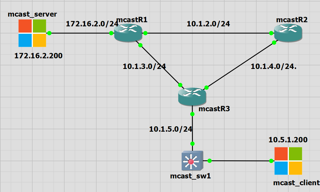
I had some trouble with this lab. The IOS switches do not seem to be truly layer 3. They have routing functionality and my mcast_switch is taking part in EIGRP. However if I use it as the default gateway for my mcast_client PC on a 172.x.x.x network then the switch is not able to route the traffic through itself. So I have left it as a L2 switch for the mcast_client PC as the default gateway is R3 10.1.5.1.
The mcast_switch is taking part in EIGRP routing, knows about the RP of 10.1.1.1 on R2 and has a multicast routing table.
IGMP Snooping
IGMP snooping is a feature available to switches that allows the switch to know which ports are requesting multicast traffic.
In my lab I have one client PC that is requesting the multicast traffic. By default the switch should forward the multicast frames out of all ports as it is multicast.
IGMP snooping is a way to efficiently use the switch bandwidth and to not send traffic to clients that do not want the multicast traffic at all or for certain groups.
There is a lot of good information in this Cisco article along with the differences between IGMPv1/2 and the bigger changes in IGMPv3. My IOS lab switches do not support IGMPv3 so this is something I can explore with the Nexus switches.
I already have the mcast_client PC receiving multicast traffic from the mcast_server. On the switch we can see the IGMP snooping table.
|
0 1 2 3 4 5 6 7 8 9 10 11 12 13 14 15 16 17 18 19 20 21 22 23 24 25 26 27 28 29 30 |
mcast_sw1#sh ip igmp snooping groups Vlan Group Version Port List --------------------------------------------------------- 5 239.0.1.2 v2 Et0/1 5 239.255.255.250 v2 Et0/1 mcast_sw1#sh ip igmp snooping vlan 5 detail Global IGMP Snooping configuration: ------------------------------------------- IGMP snooping : Enabled IGMPv3 snooping : Not supported Report suppression : Enabled TCN solicit query : Disabled TCN flood query count : 2 Robustness variable : 2 Last member query count : 2 Last member query interval : 1000 Vlan 5: -------- IGMP snooping : Enabled IGMPv2 immediate leave : Disabled Multicast router learning mode : pim-dvmrp CGMP interoperability mode : IGMP_ONLY Robustness variable : 2 Last member query count : 2 Last member query interval : 1000 Topology change : No |
Bootstrap Router (BSR) Rendezvous Point
BSR is a standard way for routers to determine the RP automatically.
BSR allows us to select the multicast groups that are associated with a specific RP. By default it is the entire multicast netwrk of 224.0.0.0/4.
BSR has two roles:
- Candidate BSR: The router that collects all available RPs in the network and advertises is throughout the network. Its function is similar to the mapping agent in AutoRP.
- Candidate RP: Routers that are advertising themselves to become the RP
In this lab I have removed the static RP I sent on all routers. I have moved the IP address 10.1.1.1 to R1 to be the automatically discovered RP and R2 now has an IP of 10.2.2.1 and will be the BSR.
In summary the aim is to ;
1. Make R2 the BSR Router with an IP of 10.2.2.1
2. Make R1 the RP with an IP of 10.1.1.1
BSR Configuration
R1
|
0 1 2 3 4 5 6 7 8 9 |
interface Loopback0 ip address 10.1.1.1 255.255.255.0 ip pim sparse-mode ip pim rp-candidate Loopback0 router eigrp 1 network 10.1.1.0 0.0.0.255 |
R2
|
0 1 2 3 4 5 6 7 8 9 |
interface Loopback0 ip address 10.2.2.1 255.255.255.0 ip pim sparse-mode ip pim bsr-candidate Loopback0 0 router eigrp 1 network 10.2.2.0 0.0.0.255 |
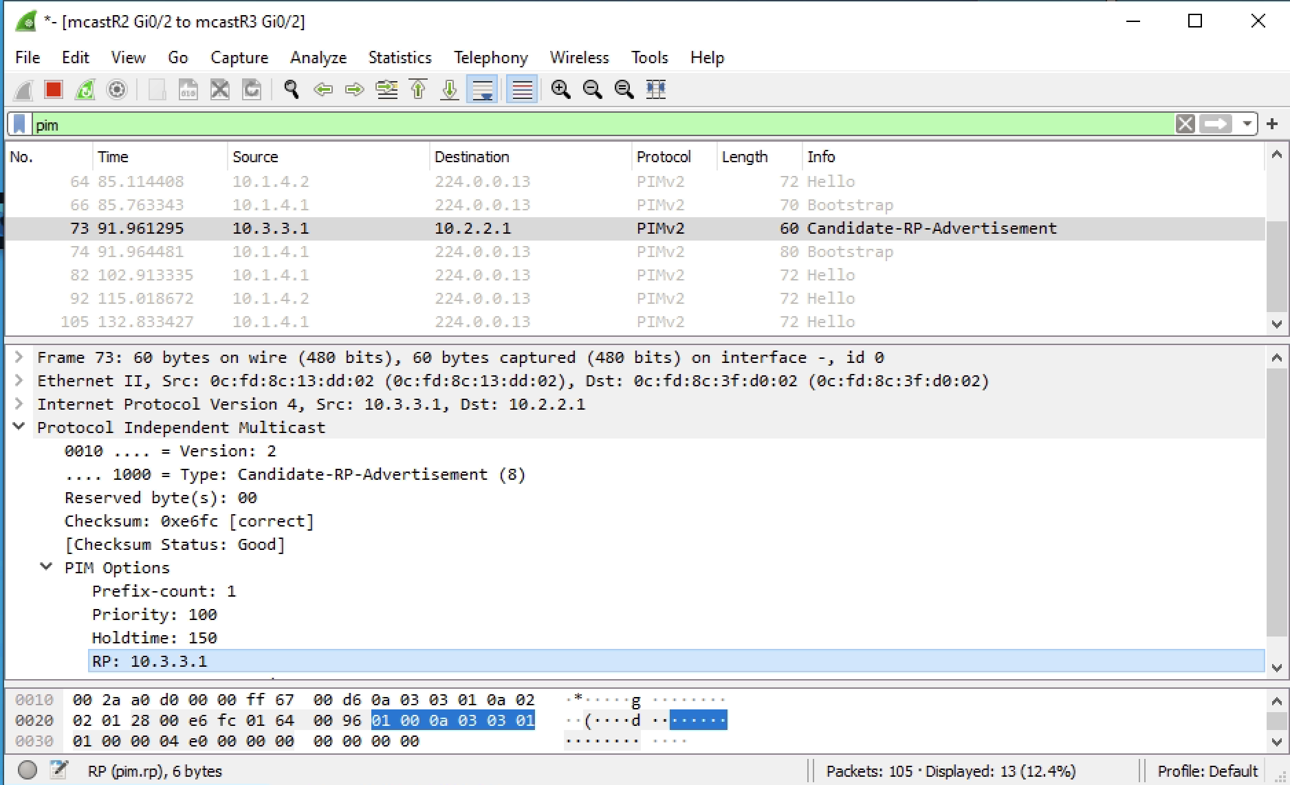
Below we can see the packet captures of; the BSR Advertisement, the RP Advertisement and the BSR advertising the RP
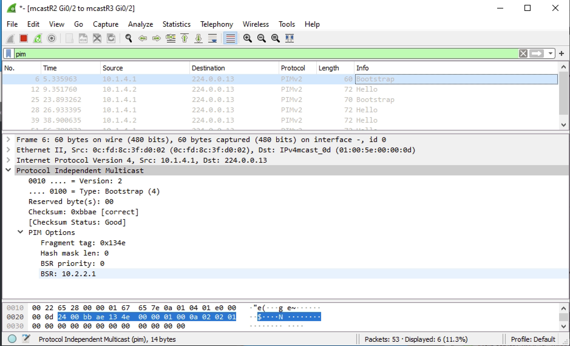
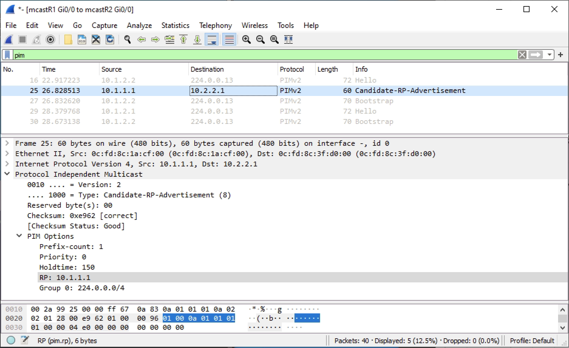
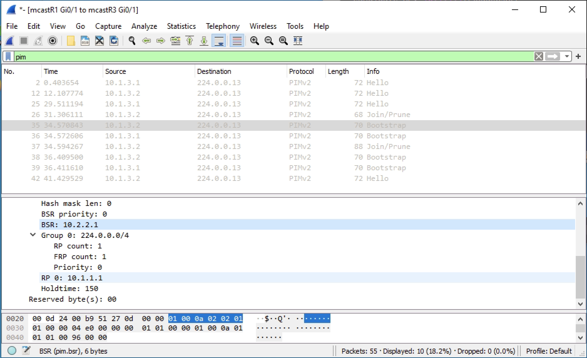
We can confirm the BSR and the RP from R3. BSR has been configured with all the defaults. So the RP is 10.1.1.1 for the entire multicast range of 224.0.0.0/4
|
0 1 2 3 4 5 6 7 8 9 10 11 12 13 14 15 |
mcastR3#sh ip pim bsr-router PIMv2 Bootstrap information BSR address: 10.2.2.1 (?) Uptime: 00:22:25, BSR Priority: 0, Hash mask length: 0 Expires: 00:01:29 mcastR3#sh ip pim rp mapping PIM Group-to-RP Mappings Group(s) 224.0.0.0/4 RP 10.1.1.1 (?), v2 Info source: 10.2.2.1 (?), via bootstrap, priority 0, holdtime 150 Uptime: 00:04:07, expires: 00:02:04 |
If traffic is sent we will see the group 239.0.1.2 and the RP for that group, which will be 10.1.1.1, but could be different if configured.
|
0 1 2 3 4 5 6 7 8 9 10 11 12 |
mcastR3#sh ip pim rp Group: 239.0.1.2, RP: 10.1.1.1, uptime 00:09:10, expires 00:02:05 Group: 239.255.255.250, RP: 10.1.1.1, uptime 00:09:10, expires 00:02:05 mcastR3#show ip pim rp-hash 239.0.1.2 RP 10.1.1.1 (?), v2 Info source: 10.2.2.1 (?), via bootstrap, priority 0, holdtime 150 Uptime: 00:10:02, expires: 00:02:12 PIMv2 Hash Value (mask 0.0.0.0) RP 10.1.1.1, via bootstrap, priority 0, hash value 1758541073 |
Adding a Second RP for Redundancy
We can add a failover here and see what happens. I will use R3 as the backup RP candidate with an IP address of 10.3.3.1.
I will shutdown R1 interface loopback0 to force the failover.
When creating R3 as a candidate RP I added a priority of 100 which makes it less preferred than R1. The BSR is advertising both RPs.
|
0 1 2 3 4 5 6 7 8 9 |
interface Loopback0 ip address 10.3.3.1 255.255.255.0 ip pim sparse-mode ip pim rp-candidate Loopback0 priority 100 router eigrp 1 network 10.3.3.0 0.0.0.255 |
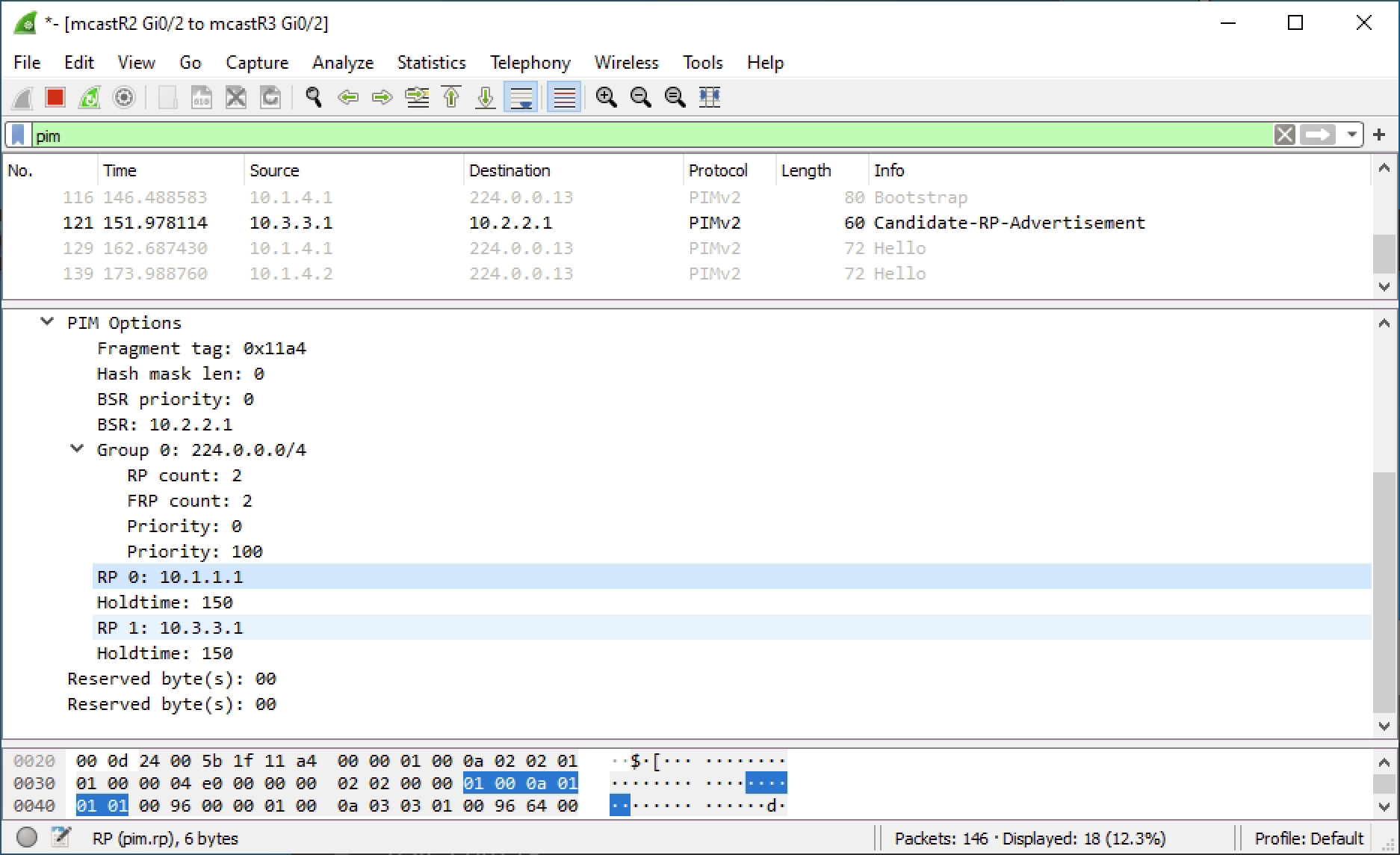
Before failover we can see that mcast_sw1 is using R1 as the RP and knows that R3 is available.
|
0 1 2 3 4 5 6 7 8 9 10 11 12 13 |
mcast_sw1#sh ip pim rp Group: 239.0.1.2, RP: 10.1.1.1, uptime 00:28:35, expires 00:01:53 Group: 239.255.255.250, RP: 10.1.1.1, uptime 00:28:35, expires 00:01:53 mcast_sw1#sh ip pim rp-hash 239.0.1.2 RP 10.1.1.1 (?), v2 Info source: 10.2.2.1 (?), via bootstrap, priority 0, holdtime 150 Uptime: 00:28:44, expires: 00:01:44 PIMv2 Hash Value (mask 0.0.0.0) RP 10.1.1.1, via bootstrap, priority 0, hash value 1758541073 RP 10.3.3.1, via bootstrap, priority 100, hash value 306712337 |
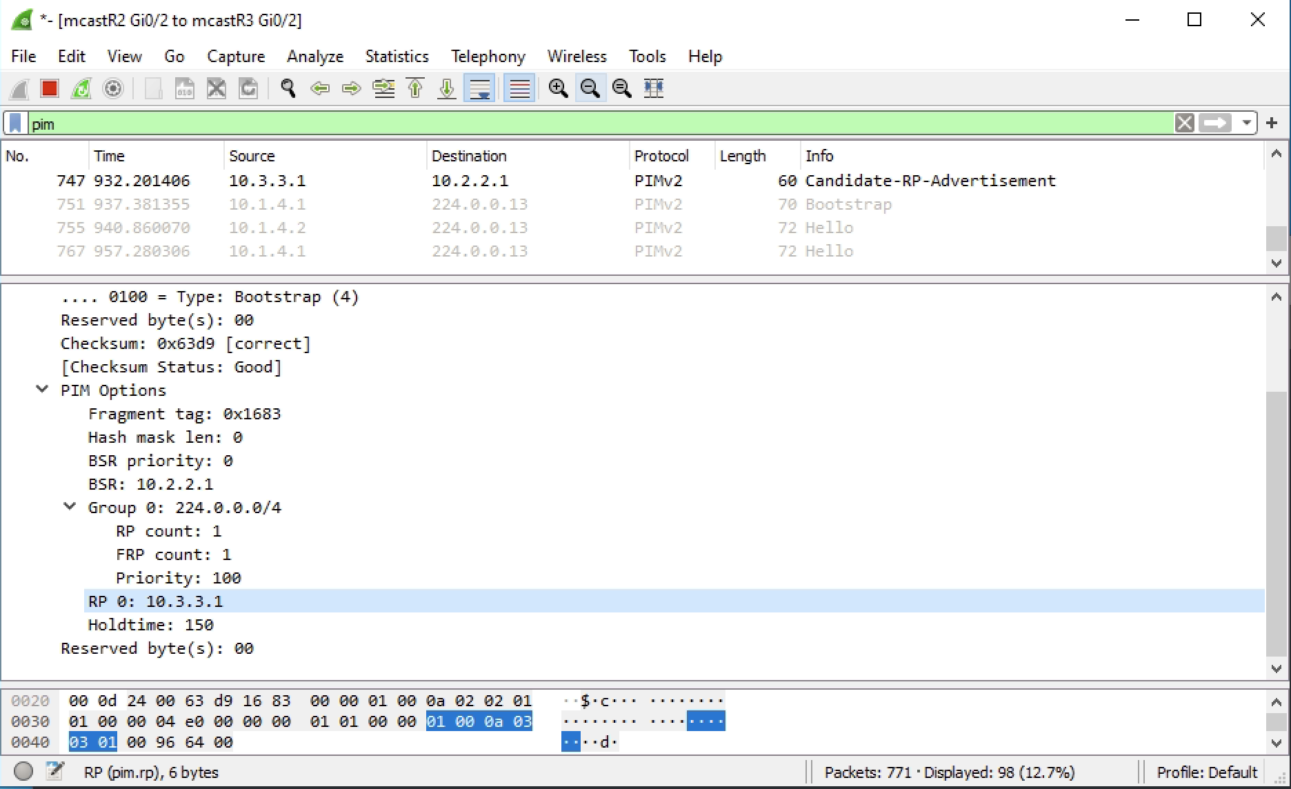
Now when R1 int lo0 is shutdown we should see the RP change to R3. I have multicast traffic currently passing and I did not see any drops. The RP did failover to R3 and this is reflected in mcast_sw1. The BSR R2 also updated the topology with the single RP of R3 10.3.3.1.
|
0 1 2 3 4 5 6 7 8 9 10 11 12 |
mcast_sw1#sh ip pim rp Group: 239.0.1.2, RP: 10.3.3.1, uptime 00:12:25, expires 00:02:06 Group: 239.255.255.250, RP: 10.3.3.1, uptime 00:12:25, expires 00:02:06 mcast_sw1#sh ip pim rp-hash 239.0.1.2 RP 10.3.3.1 (?), v2 Info source: 10.2.2.1 (?), via bootstrap, priority 100, holdtime 150 Uptime: 00:12:29, expires: 00:02:02 PIMv2 Hash Value (mask 0.0.0.0) RP 10.3.3.1, via bootstrap, priority 100, hash value 306712337 |
Useful Commands
|
0 1 2 3 4 5 |
show ip pim rp mapping show ip pim rp show ip pim bsr-router show ip pim rp-hash [multicast address] |
