
I have created an IOS15 Multicast Lab in GNS3. I have used the different PIM modes to investigate and understand how they work in my lab environment. There are some best practices when using multicast in production.
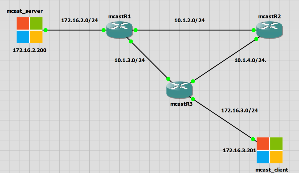
The lab is quite simple. We have a multicast server of 172.16.2.200 and a single multicast receiver of 172.16.3.201. Both are Windows servers running a multicast tester called Singleware Multicast Tester
Multicast requirements
In order to have a working multicast network we need the following requirements. I’d say the major point for a lab is a fully converged unicast routing network. For a production environment enabling multicast and enabling PIM on the correct interfaces could easily be missed.
- Fully converged unicast routing
- Multicast routing enabled
- Enable PIM on relevant interfaces
- RP configuration (sparse mode)
- Join multicast groups (testing)
Multicast Process
The multicast process is a little complex and I don’t want to explain what is already very well explained in this video
I will highlight the process that can be used for confirming and troubleshooting Multicast.
- The multicast sender is connected to R1 and has an IP of 172.16.2.200.
- The multicast receiver is connected to R3 and has an IP of 172.16.3.201
- The multicast stream is 239.0.1.2
PIM Dense Mode
PIM Dense Mode is not a recommended method for multicast traffic due to the flooding and pruning approach that it takes to forwarding multicast traffic. PIM Dense mode forces traffic to all multicast routers, meaning that we could end up with a lot of traffic flooding the network depending on the types of multicast traffic we have and how many multicast groups we have.
For me in this lab dense mode is not a problem. In a production network it is not recommended as it’s quite noisy. Dense mode is easy to setup though.
No Multicast Traffic State
We have the default Cisco group of 224.0.1.40 which is for Cisco’s Rendezvous Point discovery.
In R1 and R3 we have another group which us 239.255.255.250. I understand this to be used for Windows UPnP.
|
0 1 2 3 4 5 6 7 8 9 10 11 12 13 14 15 16 17 18 |
mcastR1#sh ip mroute Outgoing interface flags: H - Hardware switched, A - Assert winner, p - PIM Join Timers: Uptime/Expires Interface state: Interface, Next-Hop or VCD, State/Mode (*, 239.255.255.250), 00:01:10/00:02:57, RP 0.0.0.0, flags: DC Incoming interface: Null, RPF nbr 0.0.0.0 Outgoing interface list: GigabitEthernet0/0, Forward/Dense, 00:00:46/stopped GigabitEthernet0/1, Forward/Dense, 00:01:07/stopped GigabitEthernet0/3, Forward/Dense, 00:01:10/stopped (*, 224.0.1.40), 00:01:10/00:02:54, RP 0.0.0.0, flags: DCL Incoming interface: Null, RPF nbr 0.0.0.0 Outgoing interface list: GigabitEthernet0/1, Forward/Dense, 00:01:07/stopped GigabitEthernet0/0, Forward/Dense, 00:01:10/stopped |
|
0 1 2 3 4 5 6 7 8 9 10 11 |
mcastR2#sh ip mroute Outgoing interface flags: H - Hardware switched, A - Assert winner, p - PIM Join Timers: Uptime/Expires Interface state: Interface, Next-Hop or VCD, State/Mode (*, 224.0.1.40), 00:08:15/00:02:23, RP 0.0.0.0, flags: DCL Incoming interface: Null, RPF nbr 0.0.0.0 Outgoing interface list: GigabitEthernet0/2, Forward/Dense, 00:08:15/stopped GigabitEthernet0/0, Forward/Dense, 00:08:15/stopped |
|
0 1 2 3 4 5 6 7 8 9 10 11 12 13 14 15 16 17 18 19 |
mcastR3#sh ip mroute Outgoing interface flags: H - Hardware switched, A - Assert winner, p - PIM Join Timers: Uptime/Expires Interface state: Interface, Next-Hop or VCD, State/Mode (*, 239.255.255.250), 00:09:09/00:02:50, RP 0.0.0.0, flags: DC Incoming interface: Null, RPF nbr 0.0.0.0 Outgoing interface list: GigabitEthernet0/2, Forward/Dense, 00:08:51/stopped GigabitEthernet0/1, Forward/Dense, 00:09:09/stopped GigabitEthernet0/0, Forward/Dense, 00:09:09/stopped (*, 224.0.1.40), 00:09:10/00:02:54, RP 0.0.0.0, flags: DCL Incoming interface: Null, RPF nbr 0.0.0.0 Outgoing interface list: GigabitEthernet0/2, Forward/Dense, 00:08:51/stopped GigabitEthernet0/1, Forward/Dense, 00:09:10/stopped GigabitEthernet0/0, Forward/Dense, 00:09:10/stopped |
Multicast Server Transmitting
I have started the mcast_server to start send traffic. The group is 239.0.1.2. No clients are wanting to yet receive this traffic.
I am using Singleware Multicast Tester to generate the multicast traffic for this group.
We have two extra entries in the multicast routing table a *,G and S,G entry for the group 239.0.1.2
Below is the R1 mroute table
|
0 1 2 3 4 5 6 7 8 9 10 11 12 13 14 15 |
mcastR1#sh ip mroute Interface state: Interface, Next-Hop or VCD, State/Mode (*, 239.0.1.2), 00:06:02/stopped, RP 0.0.0.0, flags: D Incoming interface: Null, RPF nbr 0.0.0.0 Outgoing interface list: GigabitEthernet0/1, Forward/Dense, 00:06:02/stopped GigabitEthernet0/0, Forward/Dense, 00:06:02/stopped (172.16.2.200, 239.0.1.2), 00:06:02/00:02:44, flags: PT Incoming interface: GigabitEthernet0/3, RPF nbr 0.0.0.0 Outgoing interface list: GigabitEthernet0/0, Prune/Dense, 00:00:01/00:02:58 GigabitEthernet0/1, Prune/Dense, 00:00:01/00:02:58 |
We can see the PIM dense mode flood and prune working here. PIM Dense mode will flood the traffic for to the routers down the multicast tree every three minutes, R2 and R3 in this case.
R2 and R3 don’t yet have any clients, and therefore no need for this multicast traffic.
Every three minutes R1 will flood this multicast traffic out and we will see a prune message from R2 and R3 immediately.
The timers on the end here show the time since last flood (1 second) and timer to countdown to the next flood (2 minutes 58 seconds)
|
0 1 2 3 4 5 6 |
(172.16.2.200, 239.0.1.2), 00:06:02/00:02:44, flags: PT Incoming interface: GigabitEthernet0/3, RPF nbr 0.0.0.0 Outgoing interface list: GigabitEthernet0/0, Prune/Dense, 00:00:01/00:02:58 GigabitEthernet0/1, Prune/Dense, 00:00:01/00:02:58 |
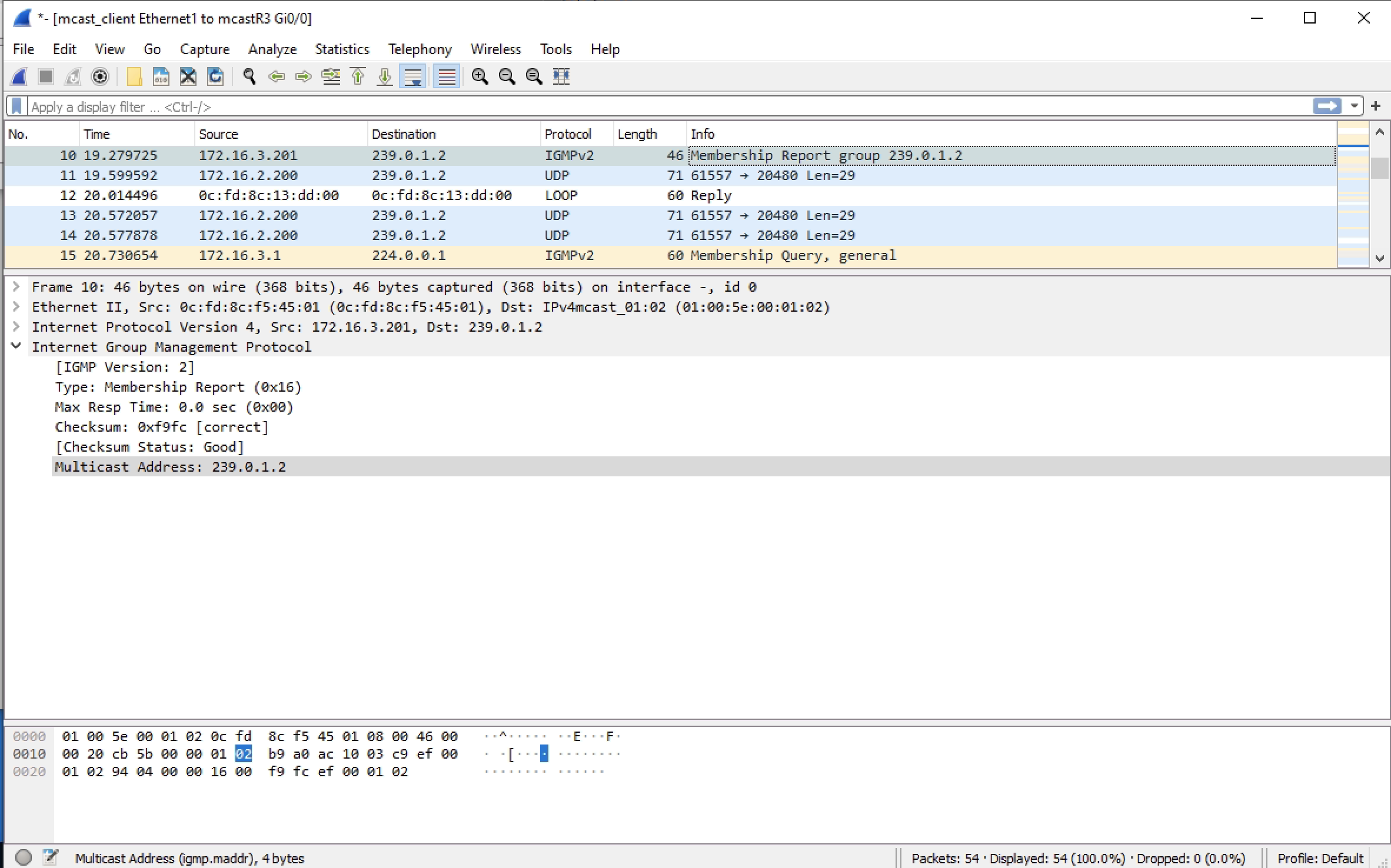
We also see the multicast traffic in Wireshark and the prune message being sent back immediately from R2/R3 to R1
Client Receiving Multicast Traffic
Now that the multicast traffic is transmitting we can introduce the client and see how this changes things.
R3 is now transmitting the traffic out of an outgoing interface. This is the interface to the mcast_client PC.
The mcast_client PC is using the same Singleware Multicast Tester software to receive the traffic.
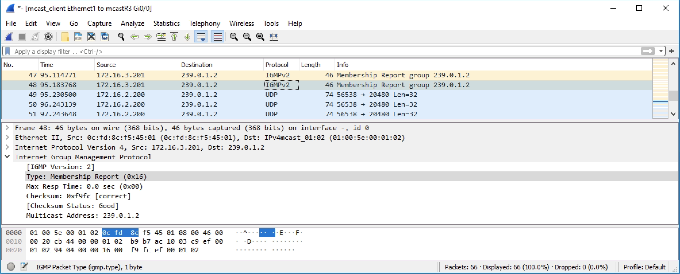
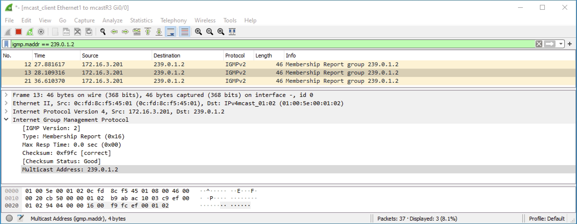
The mcast_client PC will send an IGMP join message upto the router R3 when the multicast client is run.
|
0 1 2 3 4 5 6 |
(172.16.2.200, 239.0.1.2), 00:00:49/00:02:10, flags: T Incoming interface: GigabitEthernet0/1, RPF nbr 10.1.3.1 Outgoing interface list: GigabitEthernet0/0, Forward/Dense, 00:00:14/stopped GigabitEthernet0/2, Prune/Dense, 00:00:49/00:02:10, A |
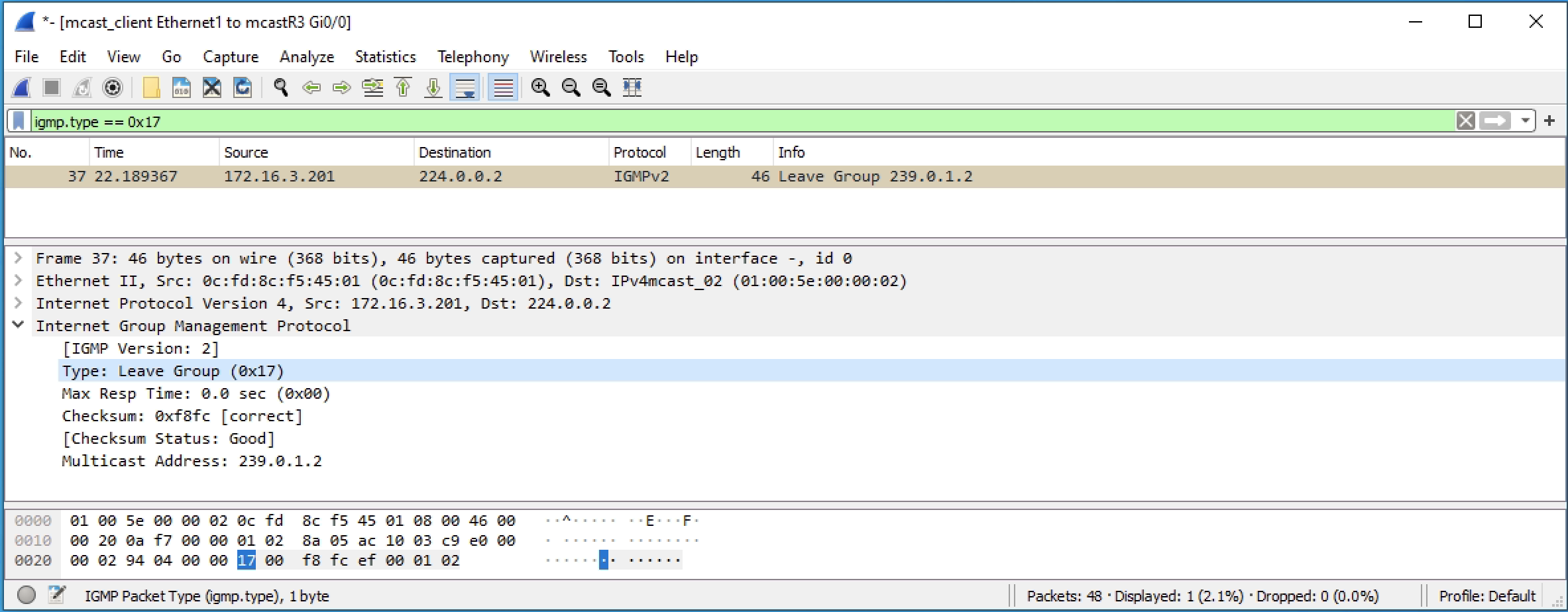
When the mcast_client doesn’t want to receive anymore multicast traffic, then it will send an IGMP leave message
Client Joining when no Multicast Transmitting
When there is no multicast traffic being sent from the mcast_server, the mcast_client can still join the group, however the R3 multicast routing table won’t have any entry for the multicast group 239.0.1.2 that is being requested.
|
0 1 2 3 4 5 6 7 8 9 10 11 12 13 14 15 16 17 18 19 20 21 22 23 24 25 26 27 |
mcastR3#sh ip mroute Outgoing interface flags: H - Hardware switched, A - Assert winner, p - PIM Join Timers: Uptime/Expires Interface state: Interface, Next-Hop or VCD, State/Mode (*, 239.0.1.2), 11:11:57/00:02:04, RP 0.0.0.0, flags: DC Incoming interface: Null, RPF nbr 0.0.0.0 Outgoing interface list: GigabitEthernet0/0, Forward/Dense, 00:02:04/stopped GigabitEthernet0/2, Forward/Dense, 11:11:57/stopped GigabitEthernet0/1, Forward/Dense, 11:11:57/stopped (*, 239.255.255.250), 11:24:59/00:02:59, RP 0.0.0.0, flags: DC Incoming interface: Null, RPF nbr 0.0.0.0 Outgoing interface list: GigabitEthernet0/2, Forward/Dense, 11:24:41/stopped GigabitEthernet0/1, Forward/Dense, 11:24:59/stopped GigabitEthernet0/0, Forward/Dense, 11:24:59/stopped (*, 224.0.1.40), 11:25:00/00:02:00, RP 0.0.0.0, flags: DCL Incoming interface: Null, RPF nbr 0.0.0.0 Outgoing interface list: GigabitEthernet0/2, Forward/Dense, 11:24:41/stopped GigabitEthernet0/1, Forward/Dense, 11:25:00/stopped GigabitEthernet0/0, Forward/Dense, 11:25:00/stopped |
Router PIM Dense Configurations
The configuration is basic and similar for all of the routers. My main points came from multicast requirements list.
R1
|
0 1 2 3 4 5 6 7 8 9 10 11 12 13 14 15 16 17 18 19 20 21 22 23 24 25 26 27 28 29 30 31 32 33 34 35 36 37 38 39 40 41 42 43 44 45 46 47 48 49 50 51 52 53 54 55 56 57 58 59 60 61 62 63 64 65 66 67 68 69 70 71 72 73 74 75 76 77 78 79 80 81 82 83 84 85 86 87 88 89 90 91 92 93 94 95 96 97 98 99 100 101 102 103 104 105 106 107 108 109 110 111 112 113 114 115 116 117 118 119 120 121 122 123 124 125 126 127 128 129 130 131 132 133 134 135 136 137 138 139 140 141 142 143 144 145 146 147 148 149 150 151 152 153 154 155 156 157 |
Building configuration... Current configuration : 3363 bytes ! ! Last configuration change at 16:27:39 UTC Mon Oct 10 2022 ! version 15.6 service timestamps debug datetime msec service timestamps log datetime msec no service password-encryption ! hostname mcastR1 ! boot-start-marker boot-end-marker ! ! ! no aaa new-model ethernet lmi ce ! ! ! mmi polling-interval 60 no mmi auto-configure no mmi pvc mmi snmp-timeout 180 ! ! ! ! ! no ip icmp rate-limit unreachable ! ! ! ! ! ! no ip domain lookup ip multicast-routing ip cef no ipv6 cef ! multilink bundle-name authenticated ! ! ! ! ! redundancy ! no cdp log mismatch duplex ! ip tcp synwait-time 5 ! ! ! ! ! ! ! ! ! ! ! ! ! interface GigabitEthernet0/0 ip address 10.1.2.1 255.255.255.0 ip pim dense-mode duplex auto speed auto media-type rj45 ! interface GigabitEthernet0/1 ip address 10.1.3.1 255.255.255.0 ip pim dense-mode duplex auto speed auto media-type rj45 ! interface GigabitEthernet0/2 no ip address shutdown duplex auto speed auto media-type rj45 ! interface GigabitEthernet0/3 ip address 172.16.2.1 255.255.255.0 ip pim dense-mode duplex auto speed auto media-type rj45 ! ! router eigrp 1 network 10.1.2.0 0.0.0.255 network 10.1.3.0 0.0.0.255 network 172.16.2.0 0.0.0.255 ! ip forward-protocol nd ! ! no ip http server no ip http secure-server ! ! ! ! control-plane ! banner exec ^C ************************************************************************** * IOSv is strictly limited to use for evaluation, demonstration and IOS * * education. IOSv is provided as-is and is not supported by Cisco's * * Technical Advisory Center. Any use or disclosure, in whole or in part, * * of the IOSv Software or Documentation to any third party for any * * purposes is expressly prohibited except as otherwise authorized by * * Cisco in writing. * **************************************************************************^C banner incoming ^C ************************************************************************** * IOSv is strictly limited to use for evaluation, demonstration and IOS * * education. IOSv is provided as-is and is not supported by Cisco's * * Technical Advisory Center. Any use or disclosure, in whole or in part, * * of the IOSv Software or Documentation to any third party for any * * purposes is expressly prohibited except as otherwise authorized by * * Cisco in writing. * **************************************************************************^C banner login ^C ************************************************************************** * IOSv is strictly limited to use for evaluation, demonstration and IOS * * education. IOSv is provided as-is and is not supported by Cisco's * * Technical Advisory Center. Any use or disclosure, in whole or in part, * * of the IOSv Software or Documentation to any third party for any * * purposes is expressly prohibited except as otherwise authorized by * * Cisco in writing. * **************************************************************************^C ! line con 0 exec-timeout 0 0 privilege level 15 logging synchronous line aux 0 exec-timeout 0 0 privilege level 15 logging synchronous line vty 0 4 login transport input none ! no scheduler allocate ! end |
R2
|
0 1 2 3 4 5 6 7 8 9 10 11 12 13 14 15 16 17 18 19 20 21 22 23 24 25 26 27 28 29 30 31 32 33 34 35 36 37 38 39 40 41 42 43 44 45 46 47 48 49 50 51 52 53 54 55 56 57 58 59 60 61 62 63 64 65 66 67 68 69 70 71 72 73 74 75 76 77 78 79 80 81 82 83 84 85 86 87 88 89 90 91 92 93 94 95 96 97 98 99 100 101 102 103 104 105 106 107 108 109 110 111 112 113 114 115 116 117 118 119 120 121 122 123 124 125 126 127 128 129 130 131 132 133 134 135 136 137 138 139 140 141 142 143 144 145 146 147 148 149 150 151 152 153 154 155 156 157 |
Building configuration... Current configuration : 3321 bytes ! ! Last configuration change at 16:27:31 UTC Mon Oct 10 2022 ! version 15.6 service timestamps debug datetime msec service timestamps log datetime msec no service password-encryption ! hostname mcastR2 ! boot-start-marker boot-end-marker ! ! ! no aaa new-model ethernet lmi ce ! ! ! mmi polling-interval 60 no mmi auto-configure no mmi pvc mmi snmp-timeout 180 ! ! ! ! ! no ip icmp rate-limit unreachable ! ! ! ! ! ! no ip domain lookup ip multicast-routing ip cef no ipv6 cef ! multilink bundle-name authenticated ! ! ! ! ! redundancy ! no cdp log mismatch duplex ! ip tcp synwait-time 5 ! ! ! ! ! ! ! ! ! ! ! ! ! interface GigabitEthernet0/0 ip address 10.1.2.2 255.255.255.0 ip pim dense-mode duplex auto speed auto media-type rj45 ! interface GigabitEthernet0/1 no ip address ip pim dense-mode shutdown duplex auto speed auto media-type rj45 ! interface GigabitEthernet0/2 ip address 10.1.4.1 255.255.255.0 ip pim dense-mode duplex auto speed auto media-type rj45 ! interface GigabitEthernet0/3 no ip address shutdown duplex auto speed auto media-type rj45 ! ! router eigrp 1 network 10.1.2.0 0.0.0.255 network 10.1.4.0 0.0.0.255 ! ip forward-protocol nd ! ! no ip http server no ip http secure-server ! ! ! ! control-plane ! banner exec ^C ************************************************************************** * IOSv is strictly limited to use for evaluation, demonstration and IOS * * education. IOSv is provided as-is and is not supported by Cisco's * * Technical Advisory Center. Any use or disclosure, in whole or in part, * * of the IOSv Software or Documentation to any third party for any * * purposes is expressly prohibited except as otherwise authorized by * * Cisco in writing. * **************************************************************************^C banner incoming ^C ************************************************************************** * IOSv is strictly limited to use for evaluation, demonstration and IOS * * education. IOSv is provided as-is and is not supported by Cisco's * * Technical Advisory Center. Any use or disclosure, in whole or in part, * * of the IOSv Software or Documentation to any third party for any * * purposes is expressly prohibited except as otherwise authorized by * * Cisco in writing. * **************************************************************************^C banner login ^C ************************************************************************** * IOSv is strictly limited to use for evaluation, demonstration and IOS * * education. IOSv is provided as-is and is not supported by Cisco's * * Technical Advisory Center. Any use or disclosure, in whole or in part, * * of the IOSv Software or Documentation to any third party for any * * purposes is expressly prohibited except as otherwise authorized by * * Cisco in writing. * **************************************************************************^C ! line con 0 exec-timeout 0 0 privilege level 15 logging synchronous line aux 0 exec-timeout 0 0 privilege level 15 logging synchronous line vty 0 4 login transport input none ! no scheduler allocate ! end |
R3
|
0 1 2 3 4 5 6 7 8 9 10 11 12 13 14 15 16 17 18 19 20 21 22 23 24 25 26 27 28 29 30 31 32 33 34 35 36 37 38 39 40 41 42 43 44 45 46 47 48 49 50 51 52 53 54 55 56 57 58 59 60 61 62 63 64 65 66 67 68 69 70 71 72 73 74 75 76 77 78 79 80 81 82 83 84 85 86 87 88 89 90 91 92 93 94 95 96 97 98 99 100 101 102 103 104 105 106 107 108 109 110 111 112 113 114 115 116 117 118 119 120 121 122 123 124 125 126 127 128 129 130 131 132 133 134 135 136 137 138 139 140 141 142 143 144 145 146 147 148 149 150 151 152 153 154 155 156 157 |
Building configuration... Current configuration : 3363 bytes ! ! Last configuration change at 16:27:27 UTC Mon Oct 10 2022 ! version 15.6 service timestamps debug datetime msec service timestamps log datetime msec no service password-encryption ! hostname mcastR3 ! boot-start-marker boot-end-marker ! ! ! no aaa new-model ethernet lmi ce ! ! ! mmi polling-interval 60 no mmi auto-configure no mmi pvc mmi snmp-timeout 180 ! ! ! ! ! no ip icmp rate-limit unreachable ! ! ! ! ! ! no ip domain lookup ip multicast-routing ip cef no ipv6 cef ! multilink bundle-name authenticated ! ! ! ! ! redundancy ! no cdp log mismatch duplex ! ip tcp synwait-time 5 ! ! ! ! ! ! ! ! ! ! ! ! ! interface GigabitEthernet0/0 ip address 172.16.3.1 255.255.255.0 ip pim dense-mode duplex auto speed auto media-type rj45 ! interface GigabitEthernet0/1 ip address 10.1.3.2 255.255.255.0 ip pim dense-mode duplex auto speed auto media-type rj45 ! interface GigabitEthernet0/2 ip address 10.1.4.2 255.255.255.0 ip pim dense-mode duplex auto speed auto media-type rj45 ! interface GigabitEthernet0/3 no ip address shutdown duplex auto speed auto media-type rj45 ! ! router eigrp 1 network 10.1.3.0 0.0.0.255 network 10.1.4.0 0.0.0.255 network 172.16.3.0 0.0.0.255 ! ip forward-protocol nd ! ! no ip http server no ip http secure-server ! ! ! ! control-plane ! banner exec ^C ************************************************************************** * IOSv is strictly limited to use for evaluation, demonstration and IOS * * education. IOSv is provided as-is and is not supported by Cisco's * * Technical Advisory Center. Any use or disclosure, in whole or in part, * * of the IOSv Software or Documentation to any third party for any * * purposes is expressly prohibited except as otherwise authorized by * * Cisco in writing. * **************************************************************************^C banner incoming ^C ************************************************************************** * IOSv is strictly limited to use for evaluation, demonstration and IOS * * education. IOSv is provided as-is and is not supported by Cisco's * * Technical Advisory Center. Any use or disclosure, in whole or in part, * * of the IOSv Software or Documentation to any third party for any * * purposes is expressly prohibited except as otherwise authorized by * * Cisco in writing. * **************************************************************************^C banner login ^C ************************************************************************** * IOSv is strictly limited to use for evaluation, demonstration and IOS * * education. IOSv is provided as-is and is not supported by Cisco's * * Technical Advisory Center. Any use or disclosure, in whole or in part, * * of the IOSv Software or Documentation to any third party for any * * purposes is expressly prohibited except as otherwise authorized by * * Cisco in writing. * **************************************************************************^C ! line con 0 exec-timeout 0 0 privilege level 15 logging synchronous line aux 0 exec-timeout 0 0 privilege level 15 logging synchronous line vty 0 4 login transport input none ! no scheduler allocate ! end |
PIM Sparse Mode
Sparse mode is different to the flooding and pruning that dense mode offers. In summary sparse mode will request the multicast traffic in a more efficient method than the flood prune of dense mode. Sparse mode is generally recommended.
With Sparse mode you need a rendezvous point (RP). This may be configured automatically or statically. Whichever method the RP must be known by all of the routers participating in multicast.
The configuration follows a similar configuration as in dense mode. The major differences are the interface commands contain “sparse” and not “dense”. And there is rendezvous to be configured.
The below routers outputs show the Ver/Mode column to be D for dense or S for sparse.
|
0 1 2 3 4 5 6 7 8 |
mcastR1#sh ip pim interface Address Interface Ver/ Nbr Query DR DR Mode Count Intvl Prior 10.1.2.1 GigabitEthernet0/0 v2/D 1 30 1 10.1.2.2 10.1.3.1 GigabitEthernet0/1 v2/D 1 30 1 10.1.3.2 172.16.2.1 GigabitEthernet0/3 v2/D 0 30 1 172.16.2.1 |
|
0 1 2 3 4 5 6 7 8 |
mcastR1#sh ip pim interface Address Interface Ver/ Nbr Query DR DR Mode Count Intvl Prior 10.1.2.1 GigabitEthernet0/0 v2/S 1 30 1 10.1.2.2 10.1.3.1 GigabitEthernet0/1 v2/S 1 30 1 10.1.3.2 172.16.2.1 GigabitEthernet0/3 v2/S 0 30 1 172.16.2.1 |
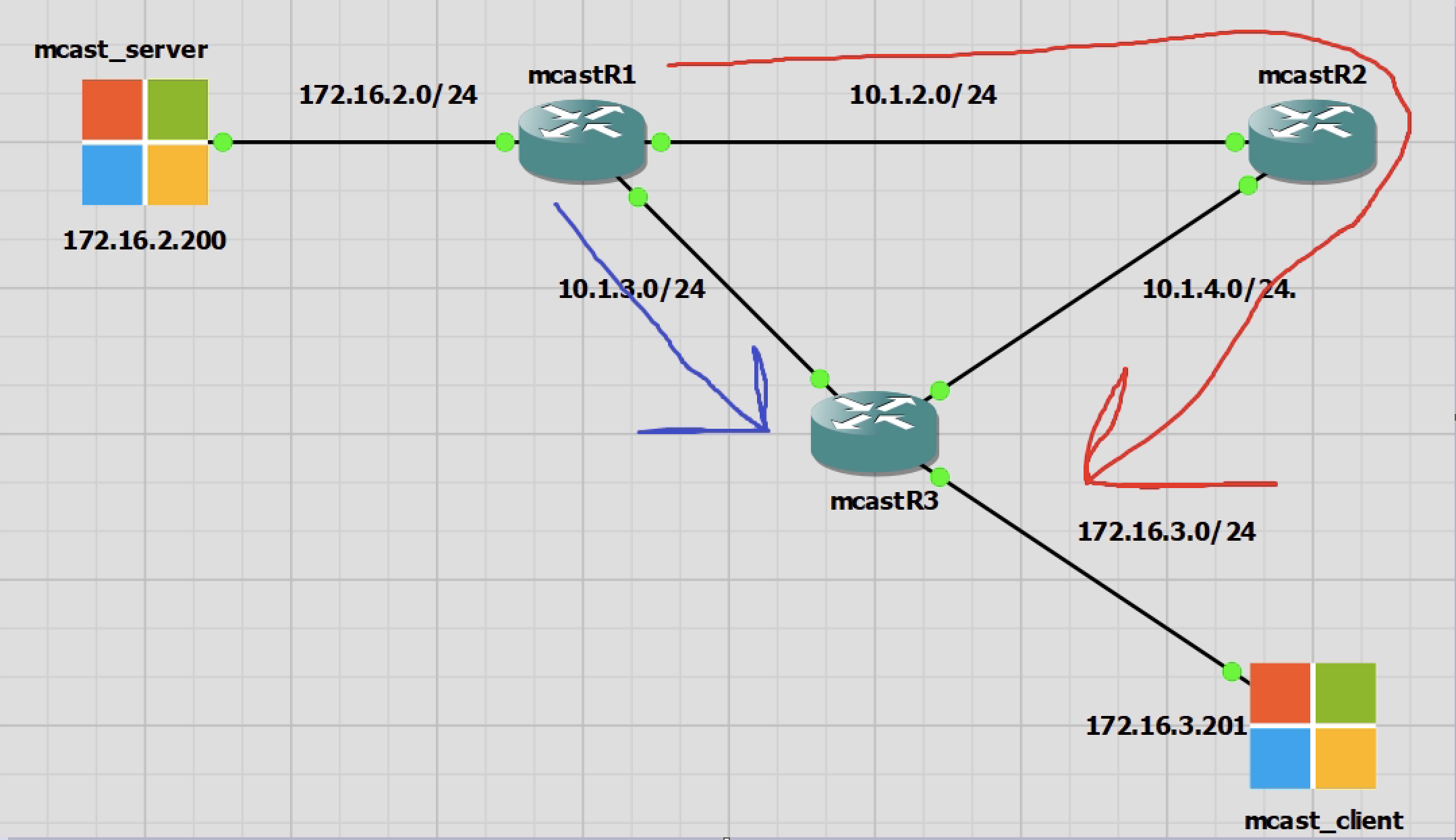
I will use a static RP for this part of the lab. I will make it R2. Not because it is the best, but to see how the shared tree and source trees work.
In brief the shared tree is multicast via the RP always, which is not always the best path. And the source tree is the client router, R3, knowing that the best path to the multicast server, is directly to R1 and no via R2.
The RP is interface lo10 on R2 using IP 10.1.1.1. This has also been added to EIGRP. All routers can ping 10.1.1.1
No Multicast Traffic State
This is the same as how PIM dense mode looked. Has the same default groups. Only difference is there is no flood/prune happening and the output references sparse mode.
|
0 1 2 3 4 5 6 7 8 9 10 11 12 13 14 |
mcastR1#sh ip mroute Outgoing interface flags: H - Hardware switched, A - Assert winner, p - PIM Join Timers: Uptime/Expires Interface state: Interface, Next-Hop or VCD, State/Mode (*, 239.255.255.250), 00:21:00/00:02:02, RP 10.1.1.1, flags: SJC Incoming interface: GigabitEthernet0/0, RPF nbr 10.1.2.2 Outgoing interface list: GigabitEthernet0/3, Forward/Sparse, 00:21:00/00:02:02 (*, 224.0.1.40), 12:06:01/00:02:31, RP 10.1.1.1, flags: SJPL Incoming interface: GigabitEthernet0/0, RPF nbr 10.1.2.2 Outgoing interface list: Null |
|
0 1 2 3 4 5 6 7 8 9 10 11 12 13 14 15 16 17 |
mcastR2#sh ip mroute Outgoing interface flags: H - Hardware switched, A - Assert winner, p - PIM Join Timers: Uptime/Expires Interface state: Interface, Next-Hop or VCD, State/Mode (*, 239.255.255.250), 00:08:29/00:02:52, RP 10.1.1.1, flags: S Incoming interface: Null, RPF nbr 0.0.0.0 Outgoing interface list: GigabitEthernet0/0, Forward/Sparse, 00:07:46/00:02:36 GigabitEthernet0/2, Forward/Sparse, 00:08:29/00:02:52 (*, 224.0.1.40), 12:05:41/00:02:55, RP 10.1.1.1, flags: SJCL Incoming interface: Null, RPF nbr 0.0.0.0 Outgoing interface list: GigabitEthernet0/2, Forward/Sparse, 12:05:41/00:02:55 GigabitEthernet0/0, Forward/Sparse, 12:05:41/00:02:25 |
|
0 1 2 3 4 5 6 7 8 9 10 11 12 13 14 15 16 |
mcastR3#sh ip mroute Outgoing interface flags: H - Hardware switched, A - Assert winner, p - PIM Join Timers: Uptime/Expires Interface state: Interface, Next-Hop or VCD, State/Mode (*, 239.255.255.250), 00:19:07/00:01:52, RP 10.1.1.1, flags: SJC Incoming interface: GigabitEthernet0/2, RPF nbr 10.1.4.1 Outgoing interface list: GigabitEthernet0/0, Forward/Sparse, 00:19:07/00:01:52 (*, 224.0.1.40), 12:06:07/00:02:57, RP 10.1.1.1, flags: SJCL Incoming interface: GigabitEthernet0/2, RPF nbr 10.1.4.1 Outgoing interface list: GigabitEthernet0/1, Forward/Sparse, 12:06:07/00:02:50 GigabitEthernet0/0, Forward/Sparse, 12:06:07/00:02:57 |
Multicast Server Transmitting
Once I start transmitting traffic from mcast_server we start to see differences. There are no clients that are requesting the traffic just yet.
R1 send out a PIM register message to the multicast group IP of 239.0.1.2. This message only goes to the RP or 10.1.1.1 and as there are no clients to receive the traffic the RP sends back a PIM stop message to stop the multicast traffic flowing as it is no required.
R1 and R2 now both know about the multicast traffic though. It is only R3 that doesn’t have any changes to the multicast routing table.
|
0 1 2 3 4 5 6 7 8 9 10 |
mcastR1#sh ip mroute # New group added (*, 239.0.1.2), 00:02:48/stopped, RP 10.1.1.1, flags: SPF Incoming interface: GigabitEthernet0/0, RPF nbr 10.1.2.2 Outgoing interface list: Null (172.16.2.200, 239.0.1.2), 00:02:48/00:02:11, flags: PFT Incoming interface: GigabitEthernet0/3, RPF nbr 0.0.0.0 Outgoing interface list: Null |
|
0 1 2 3 4 5 6 7 8 9 |
mcastR2#sh ip mroute # New group added (*, 239.0.1.2), 00:02:52/stopped, RP 10.1.1.1, flags: SP Incoming interface: Null, RPF nbr 0.0.0.0 Outgoing interface list: Null (172.16.2.200, 239.0.1.2), 00:02:52/00:02:07, flags: P Incoming interface: GigabitEthernet0/0, RPF nbr 10.1.2.1 |
Client Receiving Multicast Traffic
In this process a lot happens very quickly. Basically three things are happening;
1. mcast_client requests to receive the multicast traffic from 239.0.1.2
2. The traffic is sent to R3 and onto mcast_client via R2 – shared tree
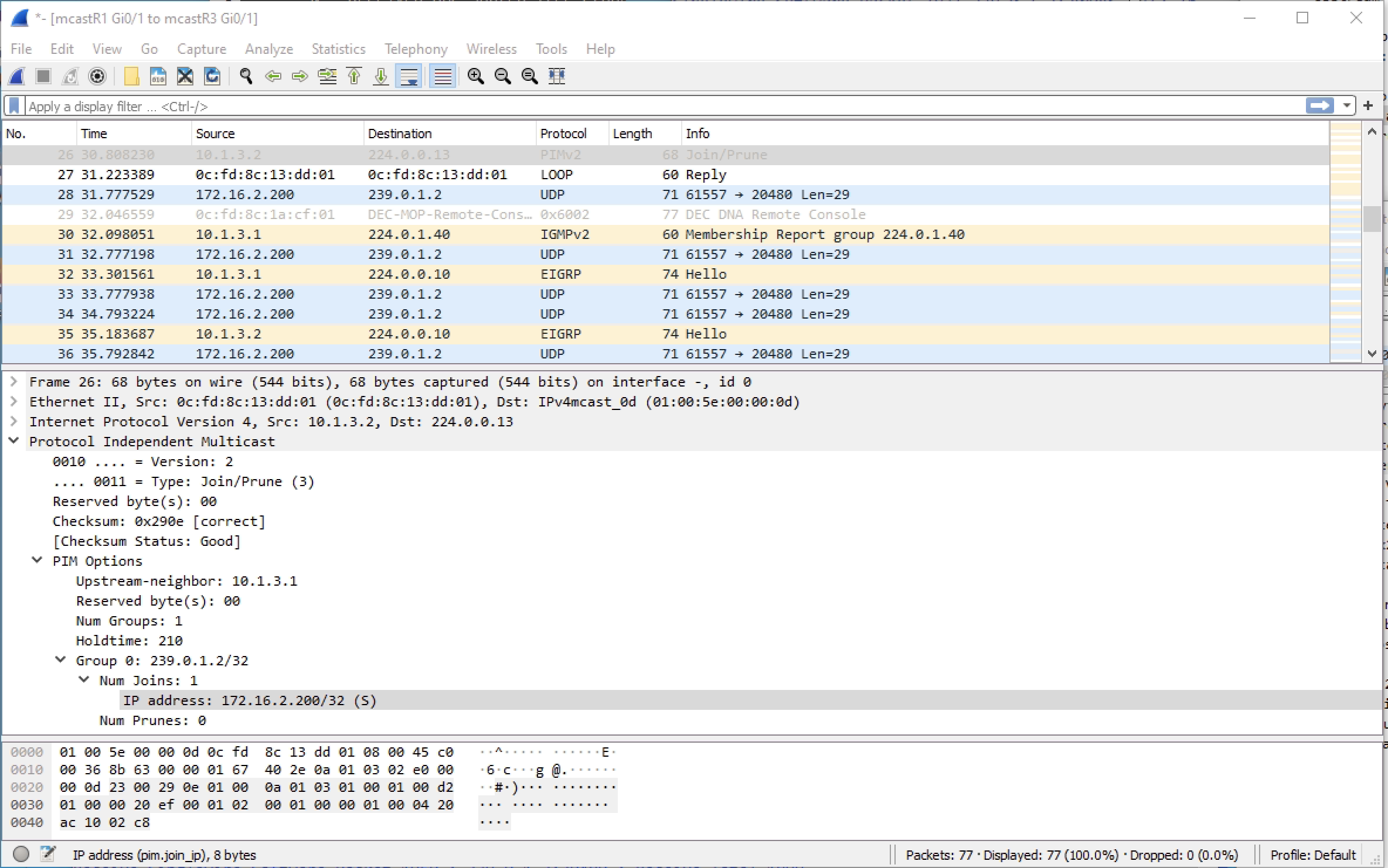
3. The traffic is found to have a more efficient path directly from R1 to R3 bypassing R2 – source tree
I’ll go into details with Wireshark captures below. Note that the routers are using the all PIM IP of 224.0.0.13 to talk to one another.
First we have mcast_client requesting to join the group 239.0.1.2.
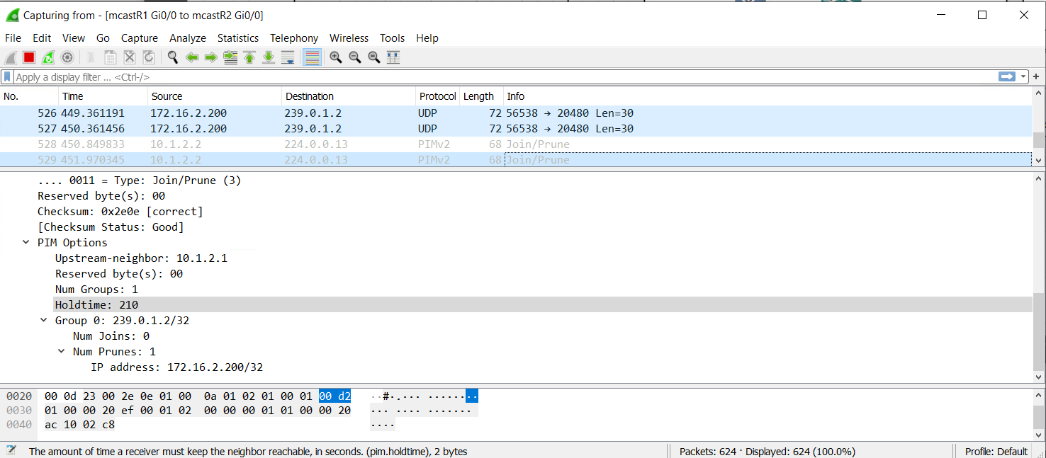
Second we have R3 joining the multicast group for the client. This is sent to the RP R2.
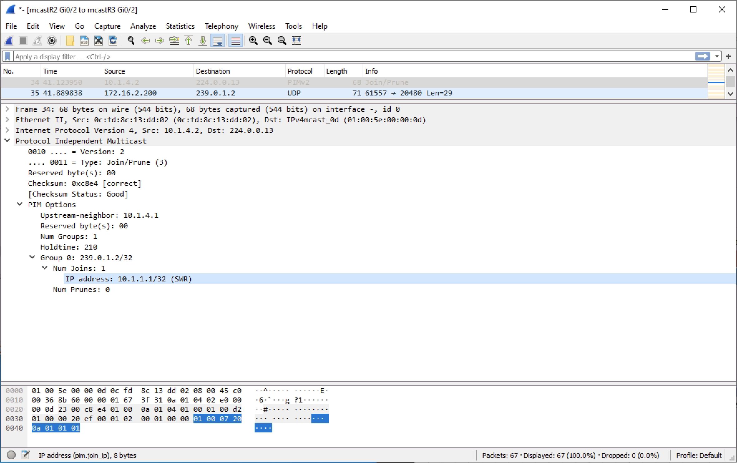
Third we have R2 sending the PIM join message to R1 to get the multicast traffic from the source.
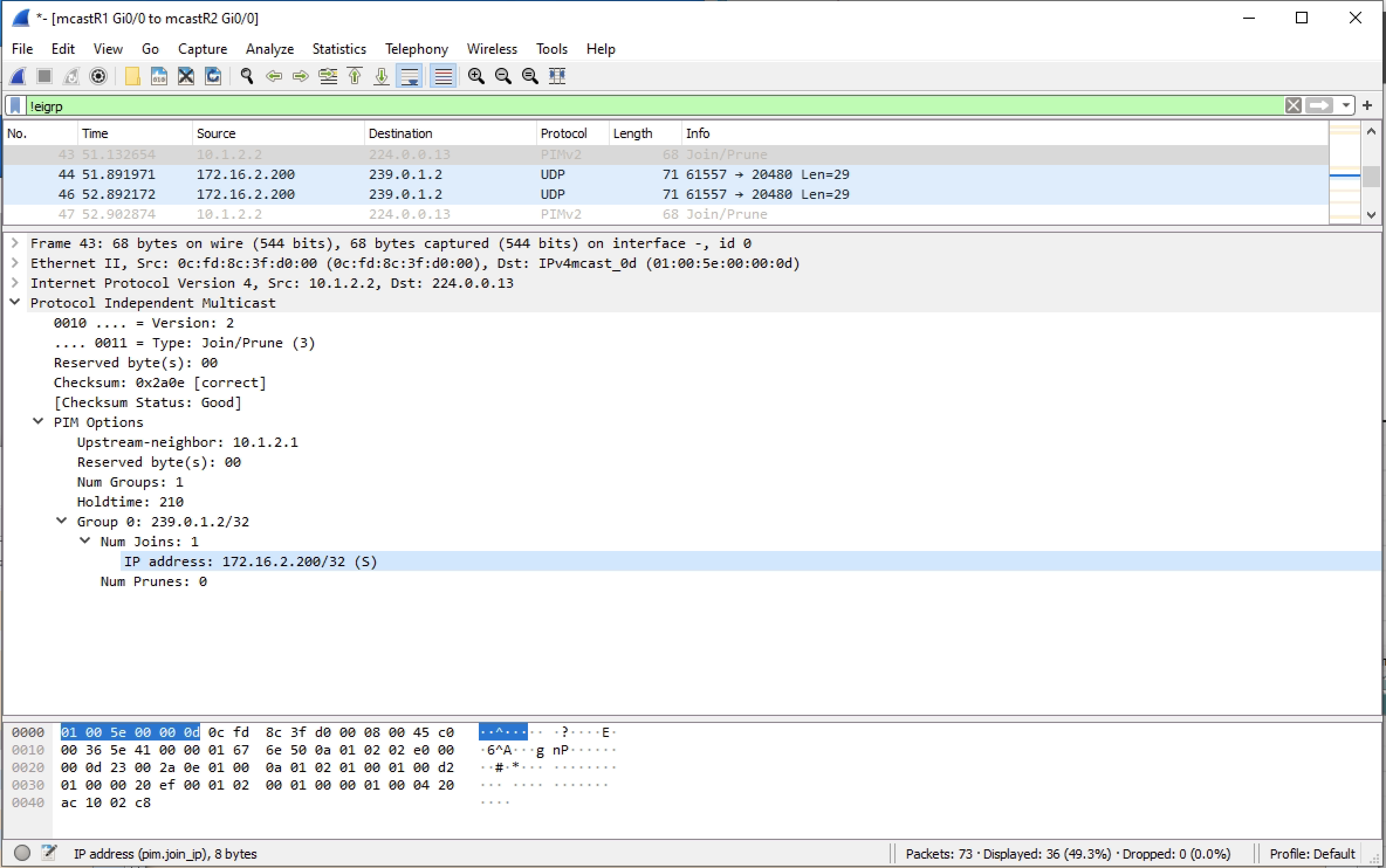
Now the traffic flows from the mcast_server to the mcast_client via R2. However this is short lived as once R3 learns the real source IP is 172.16.2.200 it looks this up in the routing table and can see a better path. This is the point there multicast switches from the shared tree via R2 to the source tree which is directly to R1.
In the diagram the shared tree is red and source tree blue
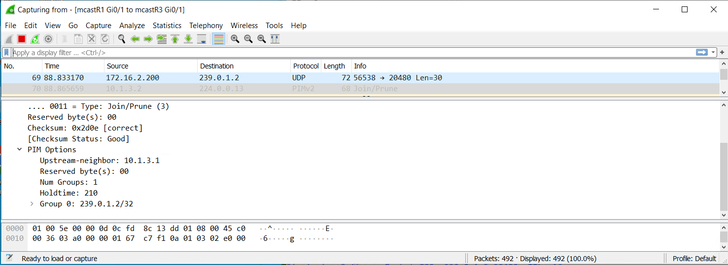
Fourth and fifth step, R3 will prune the multicast traffic upto R2, which is ther shared tree and join the better multicast traffic link to R1 which is the source tree.
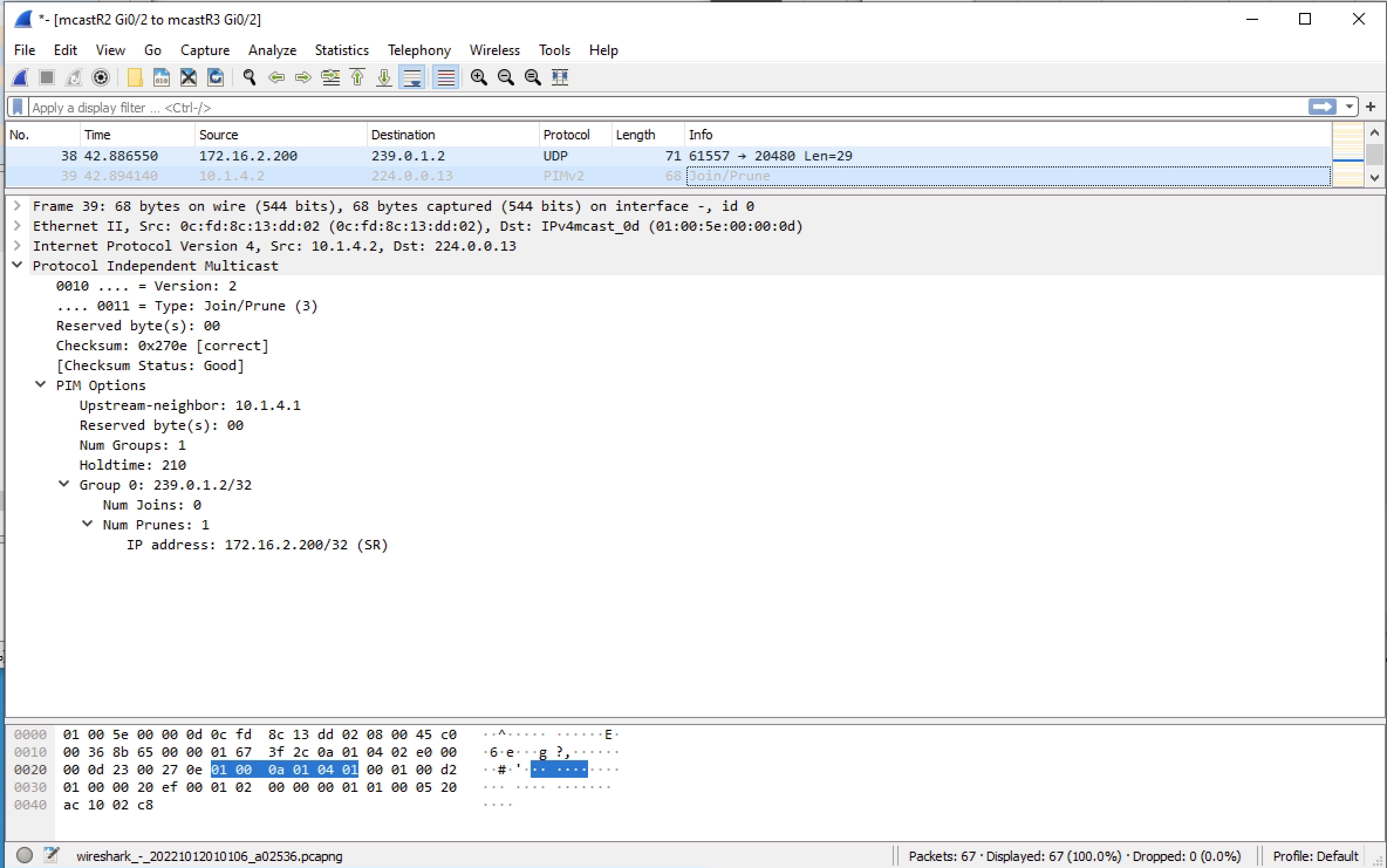
Lastly R2 will prune the multicast traffic upto R1. R2 now has no clients and therefore no need for any of the multicast traffic until it is asked again.
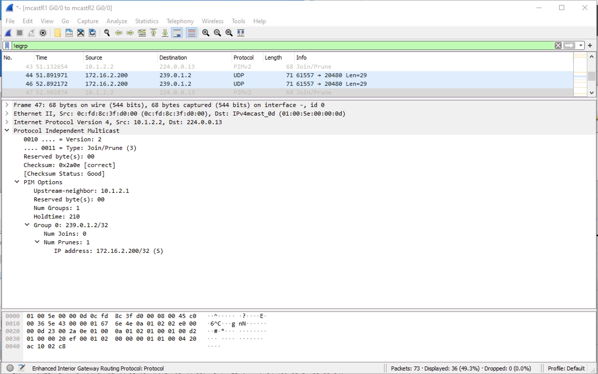
Looking at the multicast routint tables. We see that traffic is flowing from R1 to R3 directly. R2 has the *,G outgoing only and S,G incoming only. So R2 is in a state of knowing there is multicast traffic for this group, but not needing to be part of it.
|
0 1 2 3 4 5 6 7 8 9 10 |
mcastR1#sh ip mroute (*, 239.0.1.2), 00:51:03/stopped, RP 10.1.1.1, flags: SPF Incoming interface: GigabitEthernet0/0, RPF nbr 10.1.2.2 Outgoing interface list: Null (172.16.2.200, 239.0.1.2), 00:51:03/00:03:05, flags: FT Incoming interface: GigabitEthernet0/3, RPF nbr 0.0.0.0 Outgoing interface list: GigabitEthernet0/1, Forward/Sparse, 00:39:25/00:03:29 |
|
0 1 2 3 4 5 6 7 8 9 10 |
mcastR2#sh ip mroute (*, 239.0.1.2), 00:50:57/00:02:31, RP 10.1.1.1, flags: S Incoming interface: Null, RPF nbr 0.0.0.0 Outgoing interface list: GigabitEthernet0/2, Forward/Sparse, 00:39:19/00:02:31 (172.16.2.200, 239.0.1.2), 00:50:57/00:02:41, flags: PT Incoming interface: GigabitEthernet0/0, RPF nbr 10.1.2.1 Outgoing interface list: Null |
|
0 1 2 3 4 5 6 7 8 9 10 11 |
mcastR3#sh ip mroute (*, 239.0.1.2), 00:39:12/stopped, RP 10.1.1.1, flags: SJC Incoming interface: GigabitEthernet0/2, RPF nbr 10.1.4.1 Outgoing interface list: GigabitEthernet0/0, Forward/Sparse, 00:39:12/00:02:54 (172.16.2.200, 239.0.1.2), 00:39:12/00:01:37, flags: JT Incoming interface: GigabitEthernet0/1, RPF nbr 10.1.3.1 Outgoing interface list: GigabitEthernet0/0, Forward/Sparse, 00:39:12/00:02:54 |
Router PIM Sparse Configurations
R1
|
0 1 2 3 4 5 6 7 8 9 10 11 12 13 14 15 16 17 18 19 20 21 22 23 24 25 26 27 28 29 30 31 32 33 34 35 36 37 38 39 40 41 42 43 44 45 46 47 48 49 50 51 52 53 54 55 56 57 58 59 60 61 62 63 64 65 66 67 68 69 70 71 72 73 74 75 76 77 78 79 80 81 82 83 84 85 86 87 88 89 90 91 92 93 94 95 96 97 98 99 100 101 102 103 104 105 106 107 108 109 110 111 112 113 114 115 116 117 118 119 120 121 122 123 124 125 126 127 128 129 130 131 132 133 134 135 136 137 138 139 140 141 142 143 144 145 146 147 148 149 150 151 152 153 154 155 156 |
Current configuration : 3393 bytes ! ! Last configuration change at 23:36:18 UTC Tue Oct 11 2022 ! version 15.6 service timestamps debug datetime msec service timestamps log datetime msec no service password-encryption ! hostname mcastR1 ! boot-start-marker boot-end-marker ! ! ! no aaa new-model ethernet lmi ce ! ! ! mmi polling-interval 60 no mmi auto-configure no mmi pvc mmi snmp-timeout 180 ! ! ! ! ! no ip icmp rate-limit unreachable ! ! ! ! ! ! no ip domain lookup ip multicast-routing ip cef no ipv6 cef ! multilink bundle-name authenticated ! ! ! ! ! redundancy ! no cdp log mismatch duplex ! ip tcp synwait-time 5 ! ! ! ! ! ! ! ! ! ! ! ! ! interface GigabitEthernet0/0 ip address 10.1.2.1 255.255.255.0 ip pim sparse-mode duplex auto speed auto media-type rj45 ! interface GigabitEthernet0/1 ip address 10.1.3.1 255.255.255.0 ip pim sparse-mode duplex auto speed auto media-type rj45 ! interface GigabitEthernet0/2 no ip address shutdown duplex auto speed auto media-type rj45 ! interface GigabitEthernet0/3 ip address 172.16.2.1 255.255.255.0 ip pim sparse-mode duplex auto speed auto media-type rj45 ! ! router eigrp 1 network 10.1.2.0 0.0.0.255 network 10.1.3.0 0.0.0.255 network 172.16.2.0 0.0.0.255 ! ip forward-protocol nd ! ! no ip http server no ip http secure-server ip pim rp-address 10.1.1.1 ! ! ! ! control-plane ! banner exec ^C ************************************************************************** * IOSv is strictly limited to use for evaluation, demonstration and IOS * * education. IOSv is provided as-is and is not supported by Cisco's * * Technical Advisory Center. Any use or disclosure, in whole or in part, * * of the IOSv Software or Documentation to any third party for any * * purposes is expressly prohibited except as otherwise authorized by * * Cisco in writing. * **************************************************************************^C banner incoming ^C ************************************************************************** * IOSv is strictly limited to use for evaluation, demonstration and IOS * * education. IOSv is provided as-is and is not supported by Cisco's * * Technical Advisory Center. Any use or disclosure, in whole or in part, * * of the IOSv Software or Documentation to any third party for any * * purposes is expressly prohibited except as otherwise authorized by * * Cisco in writing. * **************************************************************************^C banner login ^C ************************************************************************** * IOSv is strictly limited to use for evaluation, demonstration and IOS * * education. IOSv is provided as-is and is not supported by Cisco's * * Technical Advisory Center. Any use or disclosure, in whole or in part, * * of the IOSv Software or Documentation to any third party for any * * purposes is expressly prohibited except as otherwise authorized by * * Cisco in writing. * **************************************************************************^C ! line con 0 exec-timeout 0 0 privilege level 15 logging synchronous line aux 0 exec-timeout 0 0 privilege level 15 logging synchronous line vty 0 4 login transport input none ! no scheduler allocate ! end |
R2
|
0 1 2 3 4 5 6 7 8 9 10 11 12 13 14 15 16 17 18 19 20 21 22 23 24 25 26 27 28 29 30 31 32 33 34 35 36 37 38 39 40 41 42 43 44 45 46 47 48 49 50 51 52 53 54 55 56 57 58 59 60 61 62 63 64 65 66 67 68 69 70 71 72 73 74 75 76 77 78 79 80 81 82 83 84 85 86 87 88 89 90 91 92 93 94 95 96 97 98 99 100 101 102 103 104 105 106 107 108 109 110 111 112 113 114 115 116 117 118 119 120 121 122 123 124 125 126 127 128 129 130 131 132 133 134 135 136 137 138 139 140 141 142 143 144 145 146 147 148 149 150 151 152 153 154 155 156 157 158 159 160 |
Current configuration : 3437 bytes ! ! Last configuration change at 23:33:00 UTC Tue Oct 11 2022 ! version 15.6 service timestamps debug datetime msec service timestamps log datetime msec no service password-encryption ! hostname mcastR2 ! boot-start-marker boot-end-marker ! ! ! no aaa new-model ethernet lmi ce ! ! ! mmi polling-interval 60 no mmi auto-configure no mmi pvc mmi snmp-timeout 180 ! ! ! ! ! no ip icmp rate-limit unreachable ! ! ! ! ! ! no ip domain lookup ip multicast-routing ip cef no ipv6 cef ! multilink bundle-name authenticated ! ! ! ! ! redundancy ! no cdp log mismatch duplex ! ip tcp synwait-time 5 ! ! ! ! ! ! ! ! ! ! ! ! ! interface Loopback10 ip address 10.1.1.1 255.255.255.255 ! interface GigabitEthernet0/0 ip address 10.1.2.2 255.255.255.0 ip pim sparse-mode duplex auto speed auto media-type rj45 ! interface GigabitEthernet0/1 no ip address ip pim sparse-mode shutdown duplex auto speed auto media-type rj45 ! interface GigabitEthernet0/2 ip address 10.1.4.1 255.255.255.0 ip pim sparse-mode duplex auto speed auto media-type rj45 ! interface GigabitEthernet0/3 no ip address shutdown duplex auto speed auto media-type rj45 ! ! router eigrp 1 network 10.1.1.1 0.0.0.0 network 10.1.2.0 0.0.0.255 network 10.1.4.0 0.0.0.255 ! ip forward-protocol nd ! ! no ip http server no ip http secure-server ip pim rp-address 10.1.1.1 ! ! ! ! control-plane ! banner exec ^C ************************************************************************** * IOSv is strictly limited to use for evaluation, demonstration and IOS * * education. IOSv is provided as-is and is not supported by Cisco's * * Technical Advisory Center. Any use or disclosure, in whole or in part, * * of the IOSv Software or Documentation to any third party for any * * purposes is expressly prohibited except as otherwise authorized by * * Cisco in writing. * **************************************************************************^C banner incoming ^C ************************************************************************** * IOSv is strictly limited to use for evaluation, demonstration and IOS * * education. IOSv is provided as-is and is not supported by Cisco's * * Technical Advisory Center. Any use or disclosure, in whole or in part, * * of the IOSv Software or Documentation to any third party for any * * purposes is expressly prohibited except as otherwise authorized by * * Cisco in writing. * **************************************************************************^C banner login ^C ************************************************************************** * IOSv is strictly limited to use for evaluation, demonstration and IOS * * education. IOSv is provided as-is and is not supported by Cisco's * * Technical Advisory Center. Any use or disclosure, in whole or in part, * * of the IOSv Software or Documentation to any third party for any * * purposes is expressly prohibited except as otherwise authorized by * * Cisco in writing. * **************************************************************************^C ! line con 0 exec-timeout 0 0 privilege level 15 logging synchronous line aux 0 exec-timeout 0 0 privilege level 15 logging synchronous line vty 0 4 login transport input none ! no scheduler allocate ! end |
R3
|
0 1 2 3 4 5 6 7 8 9 10 11 12 13 14 15 16 17 18 19 20 21 22 23 24 25 26 27 28 29 30 31 32 33 34 35 36 37 38 39 40 41 42 43 44 45 46 47 48 49 50 51 52 53 54 55 56 57 58 59 60 61 62 63 64 65 66 67 68 69 70 71 72 73 74 75 76 77 78 79 80 81 82 83 84 85 86 87 88 89 90 91 92 93 94 95 96 97 98 99 100 101 102 103 104 105 106 107 108 109 110 111 112 113 114 115 116 117 118 119 120 121 122 123 124 125 126 127 128 129 130 131 132 133 134 135 136 137 138 139 140 141 142 143 144 145 146 147 148 149 150 151 152 153 154 155 156 |
Current configuration : 3393 bytes ! ! Last configuration change at 23:33:08 UTC Tue Oct 11 2022 ! version 15.6 service timestamps debug datetime msec service timestamps log datetime msec no service password-encryption ! hostname mcastR3 ! boot-start-marker boot-end-marker ! ! ! no aaa new-model ethernet lmi ce ! ! ! mmi polling-interval 60 no mmi auto-configure no mmi pvc mmi snmp-timeout 180 ! ! ! ! ! no ip icmp rate-limit unreachable ! ! ! ! ! ! no ip domain lookup ip multicast-routing ip cef no ipv6 cef ! multilink bundle-name authenticated ! ! ! ! ! redundancy ! no cdp log mismatch duplex ! ip tcp synwait-time 5 ! ! ! ! ! ! ! ! ! ! ! ! ! interface GigabitEthernet0/0 ip address 172.16.3.1 255.255.255.0 ip pim sparse-mode duplex auto speed auto media-type rj45 ! interface GigabitEthernet0/1 ip address 10.1.3.2 255.255.255.0 ip pim sparse-mode duplex auto speed auto media-type rj45 ! interface GigabitEthernet0/2 ip address 10.1.4.2 255.255.255.0 ip pim sparse-mode duplex auto speed auto media-type rj45 ! interface GigabitEthernet0/3 no ip address shutdown duplex auto speed auto media-type rj45 ! ! router eigrp 1 network 10.1.3.0 0.0.0.255 network 10.1.4.0 0.0.0.255 network 172.16.3.0 0.0.0.255 ! ip forward-protocol nd ! ! no ip http server no ip http secure-server ip pim rp-address 10.1.1.1 ! ! ! ! control-plane ! banner exec ^C ************************************************************************** * IOSv is strictly limited to use for evaluation, demonstration and IOS * * education. IOSv is provided as-is and is not supported by Cisco's * * Technical Advisory Center. Any use or disclosure, in whole or in part, * * of the IOSv Software or Documentation to any third party for any * * purposes is expressly prohibited except as otherwise authorized by * * Cisco in writing. * **************************************************************************^C banner incoming ^C ************************************************************************** * IOSv is strictly limited to use for evaluation, demonstration and IOS * * education. IOSv is provided as-is and is not supported by Cisco's * * Technical Advisory Center. Any use or disclosure, in whole or in part, * * of the IOSv Software or Documentation to any third party for any * * purposes is expressly prohibited except as otherwise authorized by * * Cisco in writing. * **************************************************************************^C banner login ^C ************************************************************************** * IOSv is strictly limited to use for evaluation, demonstration and IOS * * education. IOSv is provided as-is and is not supported by Cisco's * * Technical Advisory Center. Any use or disclosure, in whole or in part, * * of the IOSv Software or Documentation to any third party for any * * purposes is expressly prohibited except as otherwise authorized by * * Cisco in writing. * **************************************************************************^C ! line con 0 exec-timeout 0 0 privilege level 15 logging synchronous line aux 0 exec-timeout 0 0 privilege level 15 logging synchronous line vty 0 4 login transport input none ! no scheduler allocate ! end |
Troubleshooting Commands
This is not a complete list of commands to run. It is a good start to understand a topology and being troubleshooting.
|
0 1 2 3 4 5 6 7 |
show ip mroute sh ip pim neighbor sh ip pim interface show ip pim tunnel show ip pim rp clear ip mroute * |