Cisco ACI is a software defined networking solution to control the management and monitoring of a VXLAN network. I know for myself and I think it is common that ACI is confusing at first as to why it’s required and what it actually solves.
So I like to think of it as a third iteration of the DC.
- Traditional DC Network
- VXLAN DC Network
- ACI (Controller based) VXLAN DC network
The Problem with the Traditional DC
A traditional DC network will be north to south, meaning traffic will flow from the access switch to the core switch and possibly through a firewall for L2 or L3 traffic. This has a number of drawbacks such as; no predictable latency, STP is in use, VLANs need to be stretched across the fabric, limited to 4096 VLANs, L2 broadcast domains, and it’s not easy to scale.
VXLAN DC Network
A VXLAN network solves many of these problems. I have demonstrated a VXLAN network using Arista switches. A VXLAN network creates an overlay/underlay network. This allows multiple virtual overlay network to be placed on top of the physical spine/leaf topology. There are several advantages to this, including;
Scalability
VXLAN enables the creation of virtual networks overlay own the physical spine/leaf topology. It uses a 24-bit segment ID VXLAN Network Identifier (VNI) that allows for a large number of isolated virtual networks
Network Segmentation
VXLAN provides network segmentation by providing virtual network overlays. It allows for the creation of logical networks or segments that can be isolated from each other, providing enhanced security, traffic isolation, and improved network performance.
Flexibility
VXLAN offers flexibility in deploying virtualised workloads across the data centre. It decouples virtual machines (VMs) from the underlying physical network infrastructure, allowing VMs to be easily migrated between servers or data centres without the need to reconfigure the network.
Multi-tenancy
VXLAN enables multi-tenancy in data centre environments. It allows different tenants or customers to have their own isolated virtual networks, ensuring privacy and separation of traffic.
Overcoming VLAN limitations
VXLAN helps overcome the limitations of traditional VLAN-based networks, such as limited scalability due to the 4096 VLANs. A traditional DC has needed to be split into segments so the same 4096 VLANs can be used to different segments. With VXLAN, the larger VNI space allows for a significantly higher number of virtual (overlay) networks.
Interoperability
VXLAN is a standard protocol that can be used with multiple vendors. It is unlikely that different vendor equipment would be part of the same network topology, but learning VXLAN on Cisco will be similar to Arista or other vendors.
Network Virtualisation
VXLAN is a key technology for network virtualisation, enabling the creation of virtual overlays that abstract the underlying physical network.
From a technical standpoint, VXLAN removes layer 2 in the DC fabric. Everything between the spine and leaf switches is routed using load balancing BGP ECMP in my Arista lab. Other drawbacks such as; no predictable latency, stretching VLANs, L2 broadcast domains are gone. There are drawbacks to VXLAN being implemented in this way, traffic is still routed through the fabric so a firewall may still be required to deny traffic on the same VRF being routed between networks.
Another drawback is keeping the network upto date as new leaf or spines are added. If you look at my first post about VXLAN, this shows a lot of configuration that is required. For the second post, I did automate this process to create a static VXLAN network. Any additional spine of leaf switches would not be recognised by the existing switches. In my third iteration, I did come up with a method to use XMPP to run python scripts on the all switches to ensure that they were upto date and aware of each other for the VXLAN fabric to be extended.
I was pleased with this work, but it was a lot of custom configuration, which shows the drawbacks of VXLAN scalability. This is where a controller based solution can help
ACI To the Rescue?
As mentioned in the VXLAN DC drawbacks, scalability can be challenging. Each and every switch needs to know about each other, and the configuration is quite long. Any new switches need to be fully configured, and existing switches need to be reconfigured to be aware of the new switches for the extended fabric.
The idea of ACI is that it will handle the scaling of the network automatically. ACI is policy driven, meaning that when setting up ACI there is an awful lot of policies to create. They are then assigned to the physical switches. The idea is that when scaling the network as the administrator is to do is add policies to the newly discovered switches and ACI will take care of the rest.
In a traditional network, the subnet and the VLAN are tied together. L2 broadcast domain, and L3 network subnet. The example network VLAN 10 in subnet 10.10.10.0/24 has 2 servers in. These servers have QoS policies and traffic needs to reach a different network segment via a firewall or load balancer.
- If the servers in
VLAN 10need to move physically, all of the QoS policies, VLANs, port config, etc must move to the new switch also. - Any traffic between the servers in
VLAN 10is not controllable with a firewall.
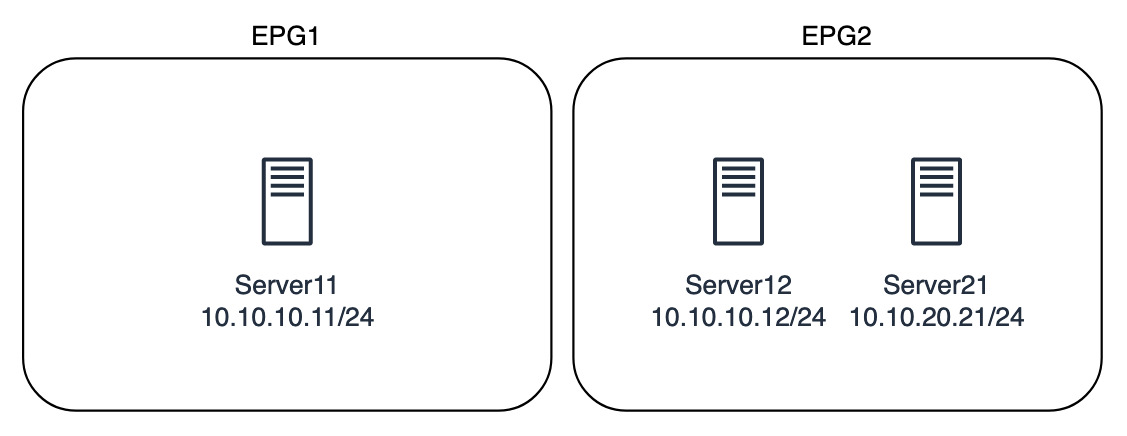
With ACI the problems in this example of reconfiguration, and firewalling are no longer issues. ACI uses logical EPGs (Endpoint Groups) as a way of grouping together similar logical endpoints, they’re technically not servers as they could be VMs, or an IP of a loadbalancer for connection to containers.
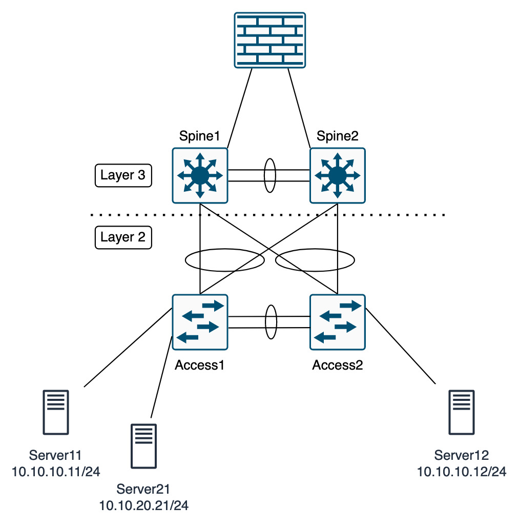
In the diagrams below, the first is the physical topology, showing that the three servers are connected to different parts of the network.
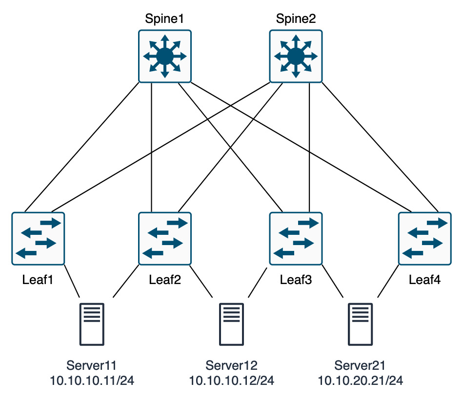
The networks and VLANs are now unimportant as they are grouped in EPGs that then control the policy. This includes ACLs, or filters inside of contracts in ACI. The image below shows EPG2 has servers from two different networks, 10.10.10.0/24 and 10.10.20.0/24.
Inside of the EPGs policies can be applied. So EPG2 will receive policies and those policies will be applied to the servers. Likewise for EPG1.
I could decide to say that Server12 and server 21 are part of the same application. Therefore, traffic between specific ports is permitted. This would be created as a policy and applied.
The server in EPG1 may well be completely self-contained and not require any access to any other servers in my network, and can be isolated.
If a server were to move physically, or even a VM migrated from one ESXi host to another, the VM details can remain the same as the policies will be applied to that VM no matter when it physically sits. That sounds more simple than traditional manual configuration.
ACI Overview
ACI has a lot of setup requirements, to get the full details, I’d recommend reading the Cisco setup example.
ACI is split into two types of configuration. The physical configuration and the logical. The easiest way to see it is that physical is more the traditional network components and the logical is the ACI policy functionality.
There is a lot to ACI. This section will be covering the more of the individual components before any configuration.
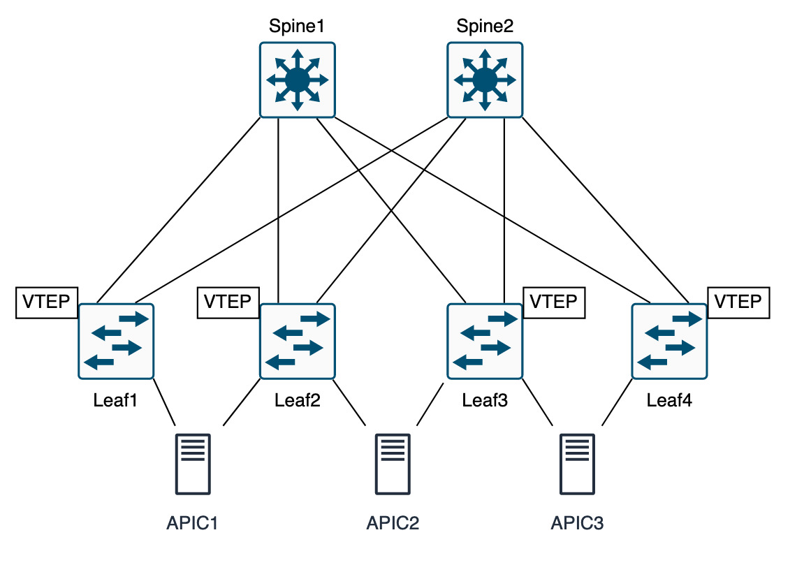
Hardware
- The ACI hardware is pretty much split into spines Nexus 9500 and leaf Nexus 9300.
- 40Gig uplinks are recommended, however any switch ending a “C” denotes that it’s 100Gig capable.
- On a basic level spines connect to leafs and leafs connect to; spines, APICs, external fabric network devices (firewall, switches, routers load balancers).
- Minimum of 3 APICs, to resolve any split brain
- Leaf switches should be in pairs for vPC
- Spines should ideally be in even numbers
Terminology
- Fabric Port: faces into the fabric, spines pointing south and leafs pointing north
- Access Ports: facing towards endpoints (external networks, APIC, servers, firewalls, storage, etc)
- Endpoints: external networks, APIC, servers, firewalls, storage, L2 or L3 connections
- Pod: group of devices making up ACI, located in same geographical location
- Extension Layer: external L3 interpod network, connect to multi site/multipod feature
- APIC: policy server config and monitoring. Maps application requirements into network config, APCI can be down and network still function, just not configured
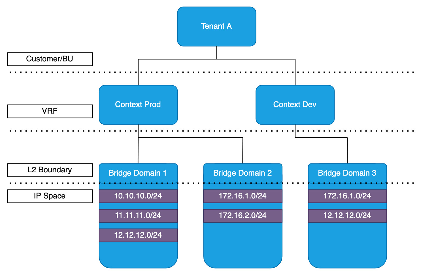
Tenants, Contexts and Bridge Domains
Tenants: relates to customer, or group etc. This is the container that everything sits in ACI. Allows for multiple tenants (customers) to use the same infrastructure. The way the cloud works.
Contexts: VRFs. Splitting the routing table into multiple routing tables per tenant. Similar to the way that has been going on for years on a more traditional network setting. Multiple contexts per Tenant is permitted for duplicate addressing. VMs can be migrated between contexts
Bridge Domains: in simple terms, these are VXLANs. They use identifiers similar to a VNI in VXLAN.
Traffic within a bridge domain is bridged, and traffic between bridge domains is routed.
Subnets are not important, as all the routing is based on /32 host routes. This will be expanded on later, but the Spine switches know all the host IPs and which leaf switch they are connected to.
Bridge domains are tied to contexts.
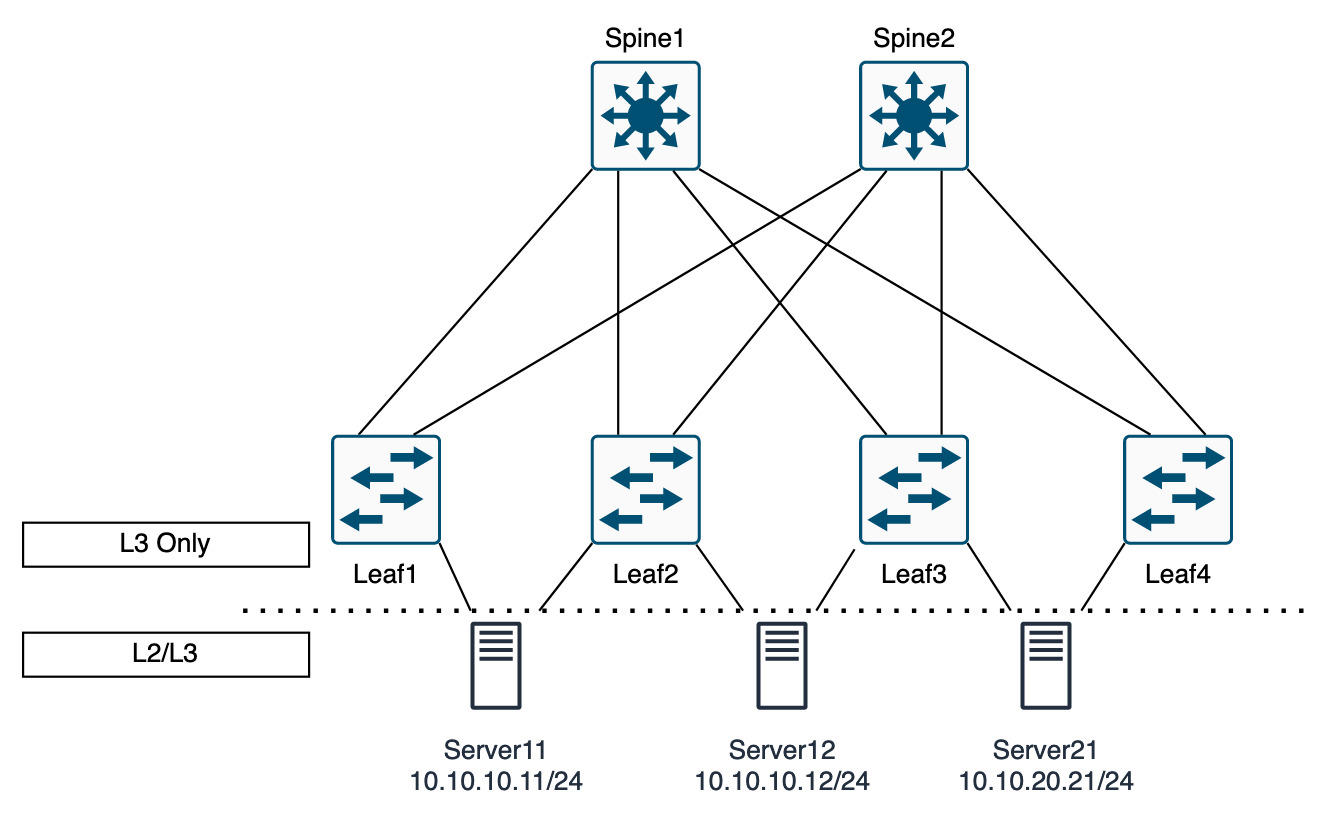
One last point on the bridge domain is that the by default L2 flooding is disabled by default. In a traditional network, L2 flooding is how ARP works and therefore how the servers find their gateways and other endpoints in their VLAN.
In ACI, flooding is not required due to the fact that when an endpoint is discovered on the network, that endpoint IP and location is announced to the spine. If another leaf wants to find that endpoint it needs to only query the spine. Removing any flooding in the fabric.
In the diagram below, this shows that the servers can use L2 to send ARPs for the gateway. The gateway for each severs network will be on each leaf switch. This is using an AnyCast gateway. As the networks operate on the underlay/overlay, each tenant network is an overlay network. The gateways only need to be reachable for the endpoints (servers in this example).
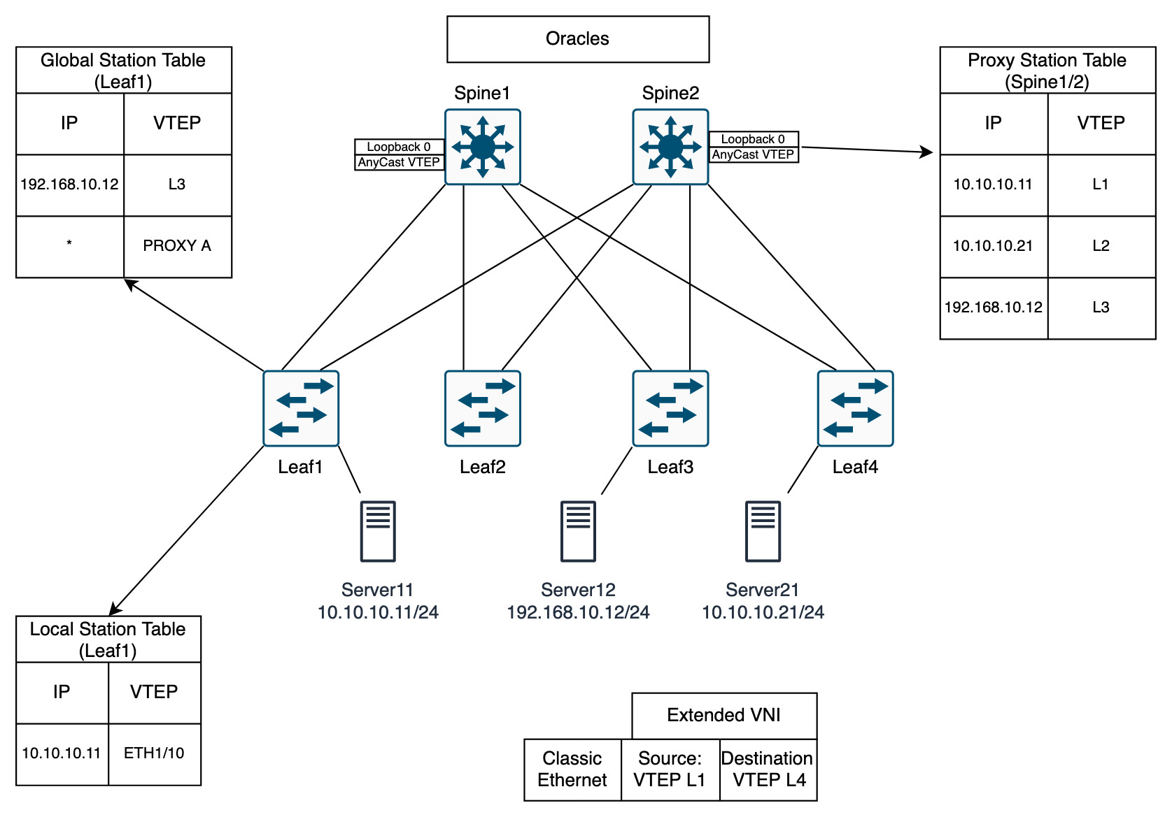
Forwarding with the ACI Fabric
This is the parts that performs the clever VXLAN functionality but in ACI. This is different to the standard VXLAN BGP EVPN. But it is essentially the same, where each switch is aware of the IP addresses of the endpoints. This allows for the IP and the location to be separated. We end up with 10.10.10.10/32 VTEP 1. If this endpoint were to move, the IP can remain the same, but the VTEP will be different.
There is a lot going on in the below diagram to explain what is happening. ACI uses a number of protocols and terms to describe the flow of traffic.
Starting with Leaf1…
- Leaf 1 has Local Station Table that contains all the endpoints connected to it
- Leaf1 has learnt about
10.10.10.11
- Leaf1 has learnt about
- Leaf 1 has Global Station Table that contains the external endpoints it knows about
- Previously
192.168.10.12has communicated to endpoint10.10.10.11on Leaf1
- Previously
- Each table has separated the IP and the location
- COOP protocol used to send learnt endpoints from the local station table to the Spines
- COOP: Council of Oracle Protocol
Spines…
- Also known as Oracles
- COOP protocol receives learnt endpoints from the leafs
- Each spine has a unique Lo0 IP
- Spines share an AnyCast VTEP
- Spines share a Proxy Station Table
Communication from Server11 to Server21
- Server recognises that it is in the same subnet, issues ARP
- Classic ethernet sent to Leaf1
- Leaf1 destination IP
10.10.10.21is not in Local Station Table - Leaf1 consults Global Station Table, nothing there either
- Leaf1 will perform a lookup for the IP
10.10.10.21to the Spines using the AnyCast VTEP- This is the function of the * PROXY A in the Global Station Table
- This can be sent out to any Spine switch
- Once the VTEP destination has been learnt as VTEP L4, the frames can be encapsulated into VXLAN
- The classic ethernet frame is encapsulated into an Extended VNI packet
- Source VTEP L1
- Destination VTEP L4
- Traffic is forwarded to Spine and to Leaf4
Distributed Gateways
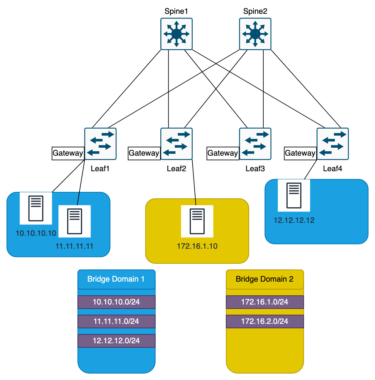
The ACI distributed gateway is the AnyCast gateway on each leaf switch. This is the network on the bridge domain. Referring back to the earlier image.
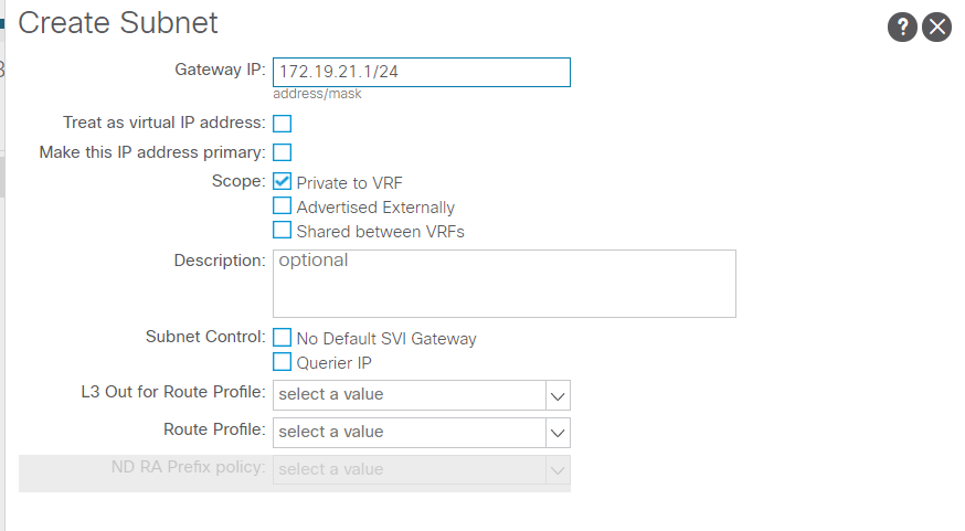
In the screenshot below from an ACI lab, creating a subnet is shown. The subnet isn’t actually created, it is the gateway IP of the Bridge Domain that is created, but that also makes the network.
The only option selected is “Private to VRF”. What this means is that this subnet 172.19.21.0/24 will not be able to leave the ACI fabric. That would be though an L2 or L3 out.
The option “Advertised Externally” is what allows for the network to leave the fabric.
The gateways are only configured on the leaf switches that contain the endpoints in the networks. In the diagram below, Leaf1 and Leaf4 have the gateways for Bridge Domain 1 and Leaf2 has the gateways for Bridge Domain 2.
Getting deeper, the gateways on Leaf1 and Leaf4 will be SVIs. These SVIs are exactly the same. So for example the gateways could be 10.10.10.1, 11.11.11.1 and 12.12.12.1. These SVIs exist on every leaf switch that has endpoints from that bridge domain. This is the policy.
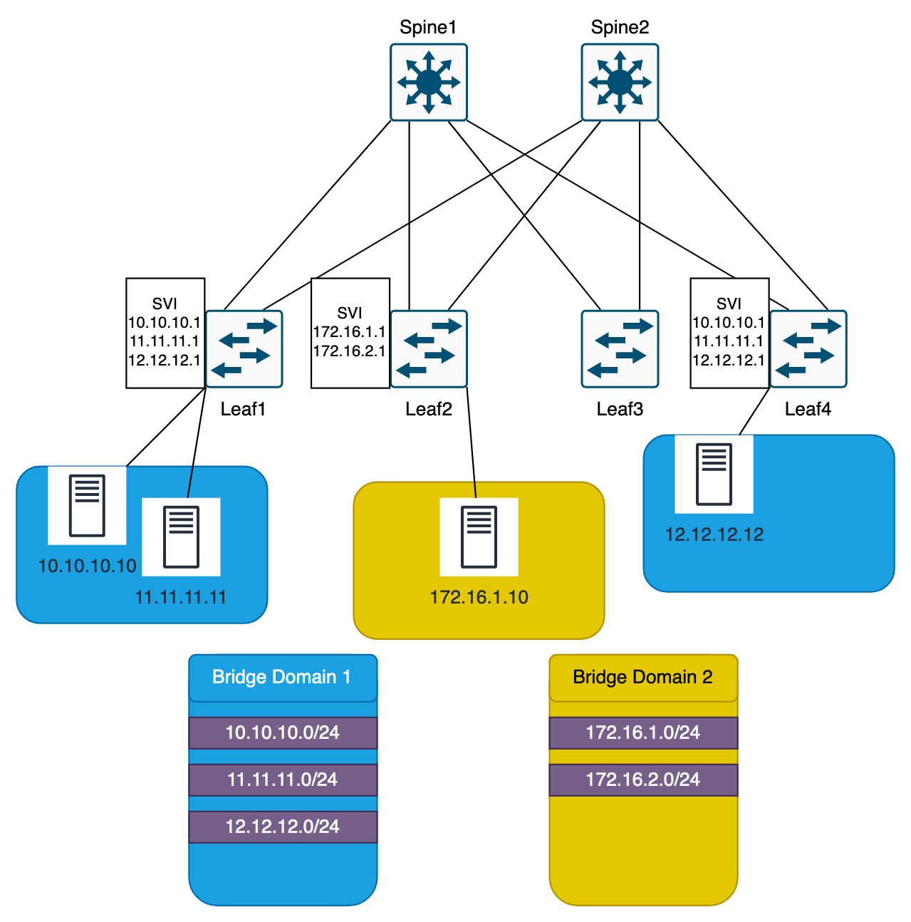
Finally, to make things even more confusing and truly breaking away from the traditional networking side, the VLAN that is associated with the networks do not need to match between Leaf1 and Leaf4.
All that needs to happen is that VLAN X is tired to Bridge Domain X and VNI X.
Leaf1 could be VLAN 10, Bridge Domain 1, VNI 1
Leaf2 VLAN 20, Bridge Domain 1, VNI 1
Only the mappings of the Bridge Domain to the VNI are now important.
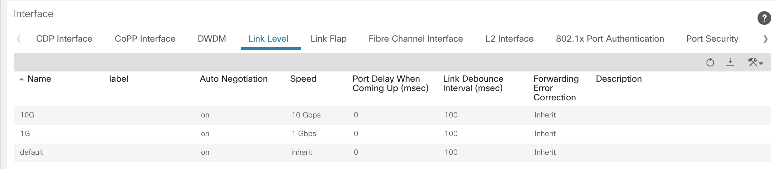
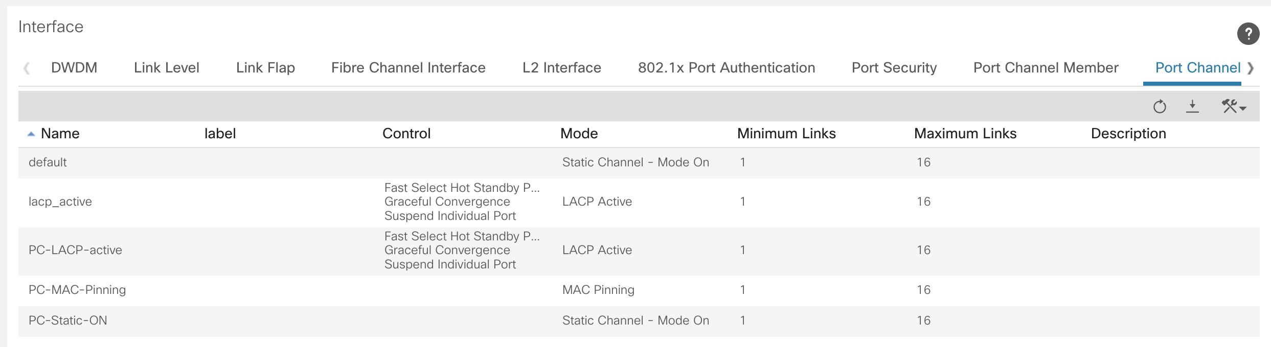
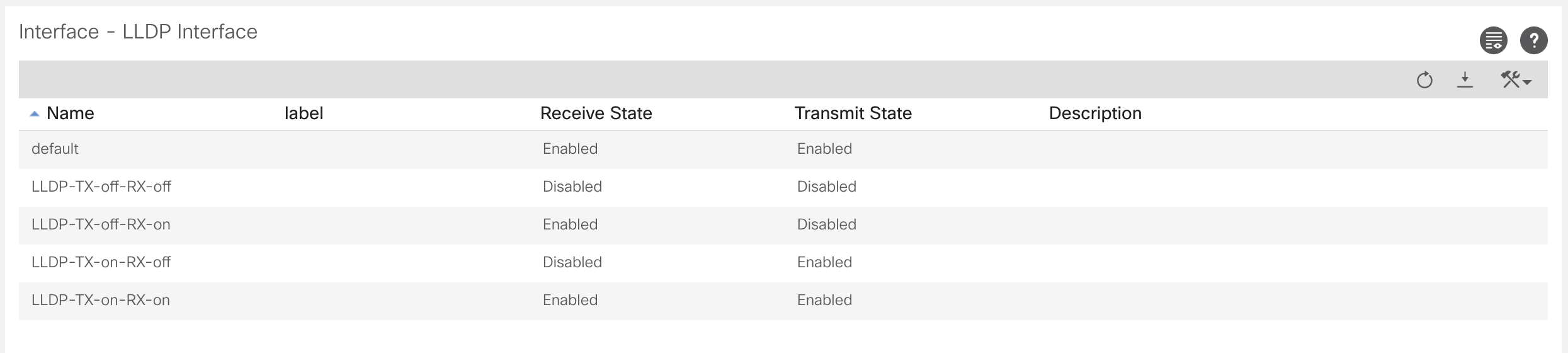
Management Protocols and Interface Policies
The interface policies are policies for the different settings on the ports. If we compare this to the traditional IOS configuration method, a way to look at the ACI interface policies are the individual commands that can be assigned to the switch port. Such configuration settings as; CDP, LLDP, LACP, STP, NTP, DNS etc.
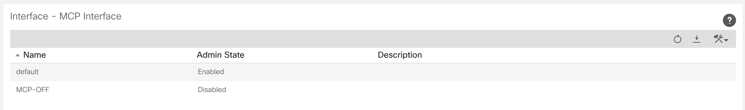
There is also MCP, which stands of miscalling protocol. This is a protocol that ACI uses to detect if a spine is directly connected to a spine or a leaf directly connected to a leaf. If the MCP detects this, it will error disable the port, as this is not permitted in the ACI fabric.
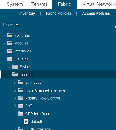
In the ACI web interface, to get to the interface policies use:Fabric >> Access Policies >> Interface Policies >> Policies
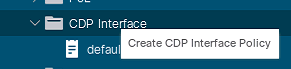
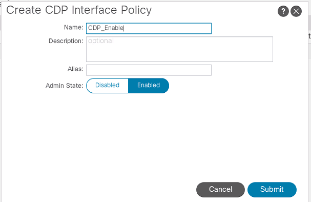
Below is an example of a CDP policy being created. Typically, the polices would all be created with what you may desire to use in the fabric before anything is done. Planning is vital for ACI.
Switch and Interface Profiles
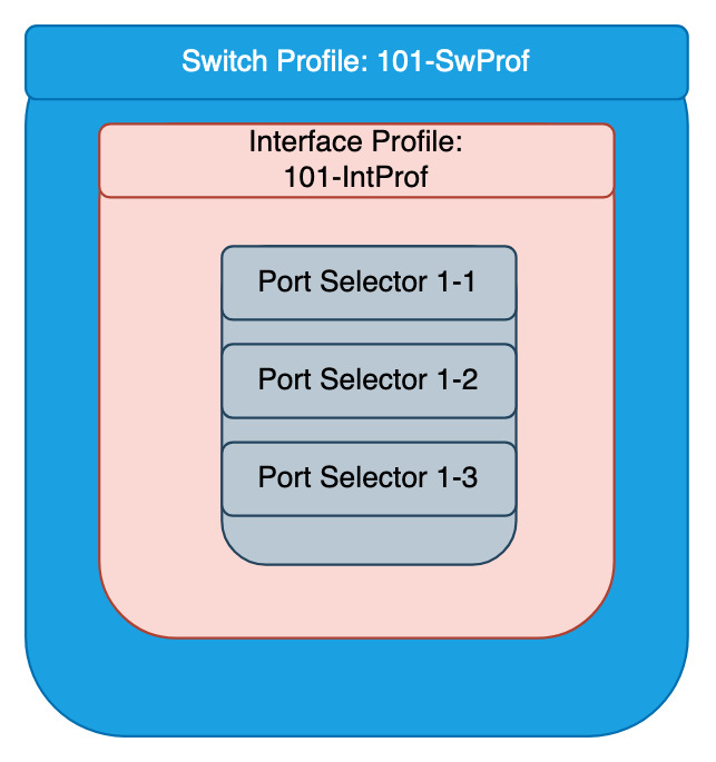
This is more policy creation that isn’t always going to be used. This is specifying there is a switch profile for leafX, and there is a switch profile for a part of leafs, leafX and leafY.
The switch profiles contain interface profiles of the physical ports on the switch and interface selectors, that pick the physical ports.
When configuring an interface selector, it is best to identify each port individually. So not do impact ports if a range were to be used and changes are required.
Switch Profile
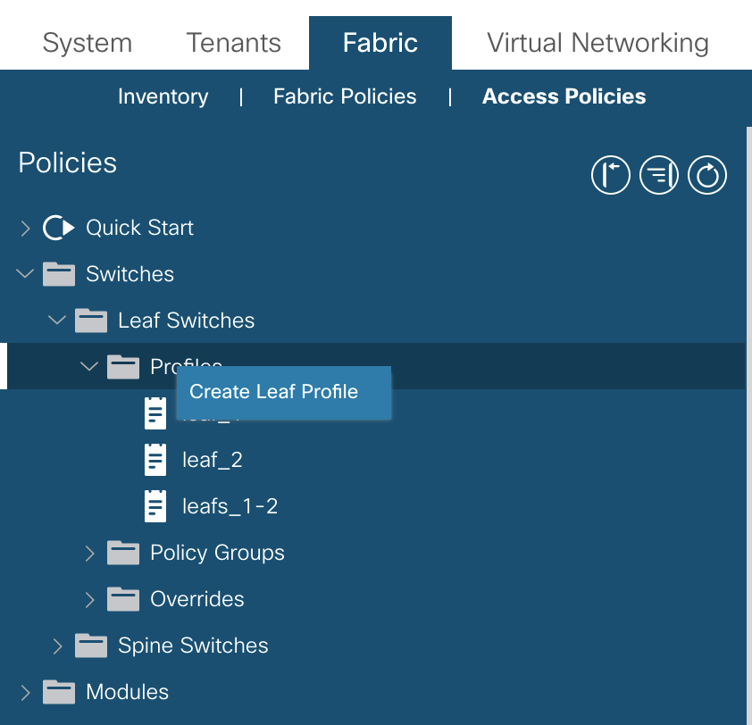
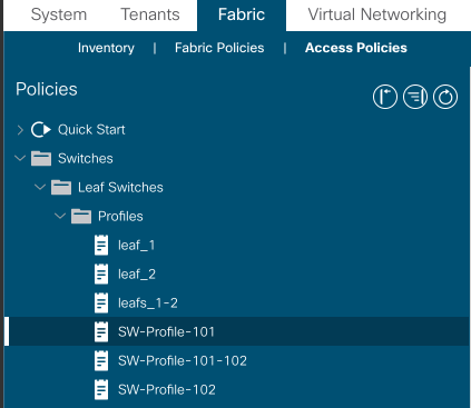
Configuration for the switch profile can be found under: Fabric >> Access Policies >> Switches >> Leaf/Spine Switches
Right click on profiles to create a new profile
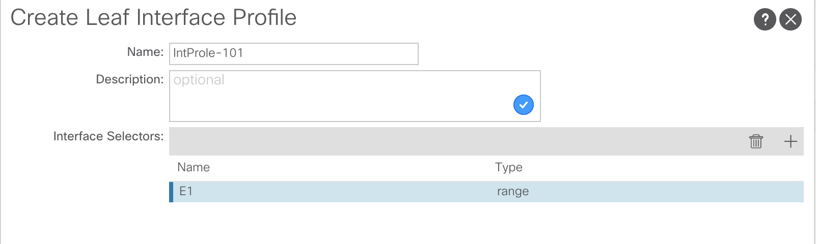
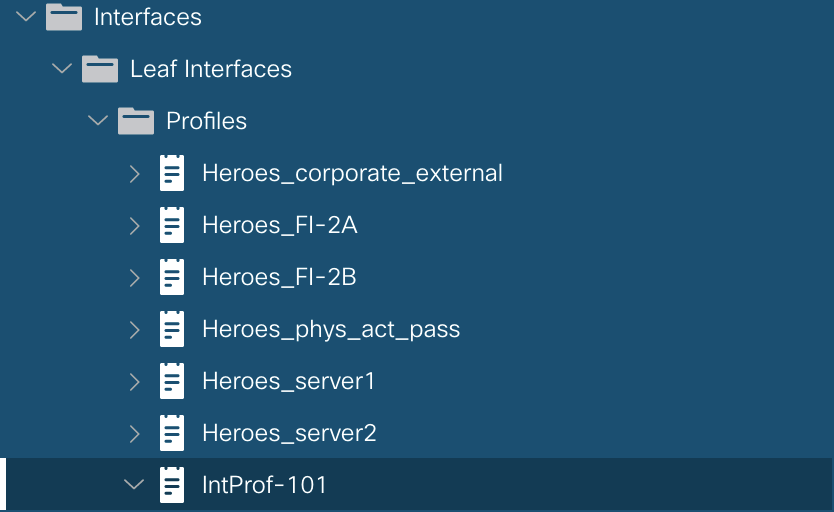
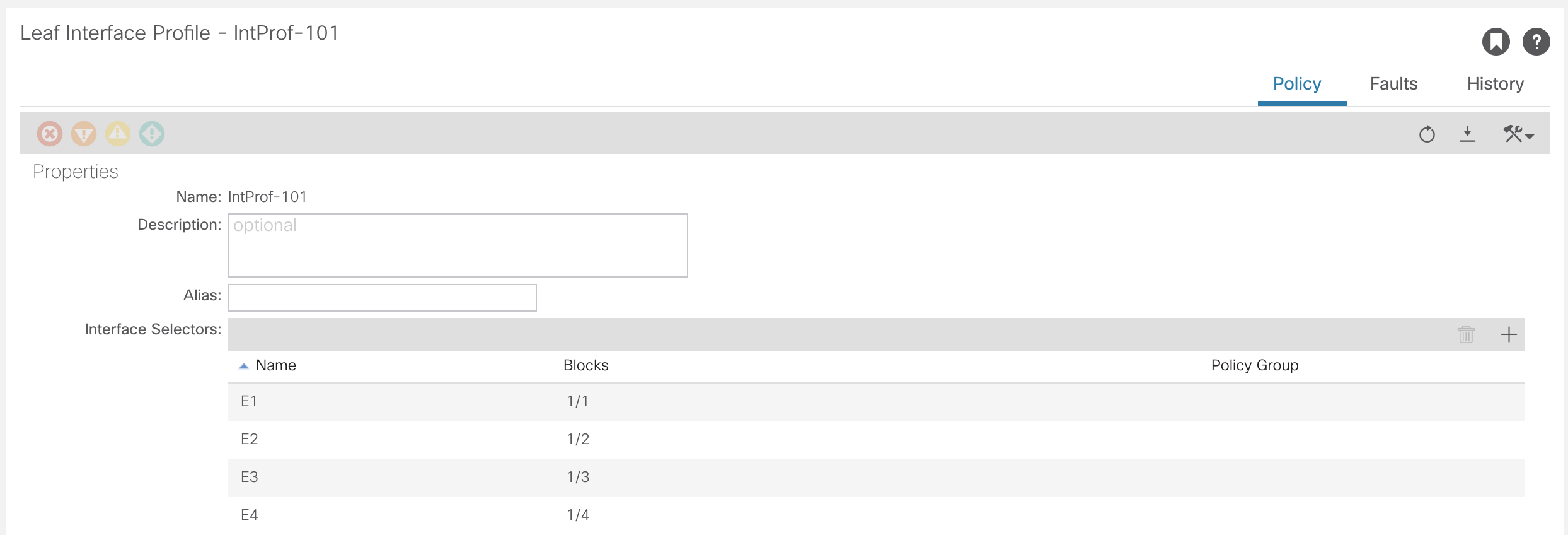
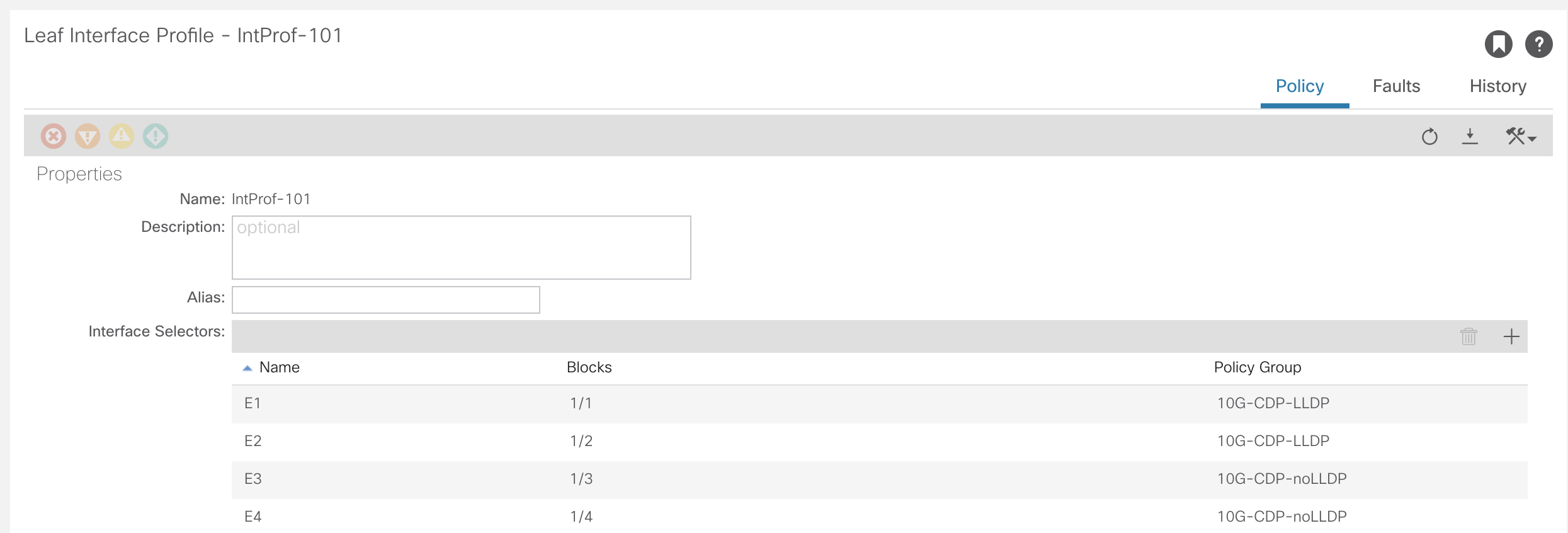
Interface Profile
This is where the interfaces on the leaf switches that are connected outside of the fabric. The configuration for the interface profiles can be found under:Fabric >> Access Policies >> Interfaces >> Leaf/Spine Interfaces >> Profiles
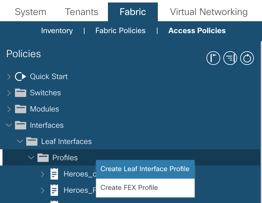
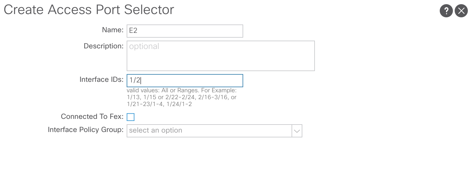
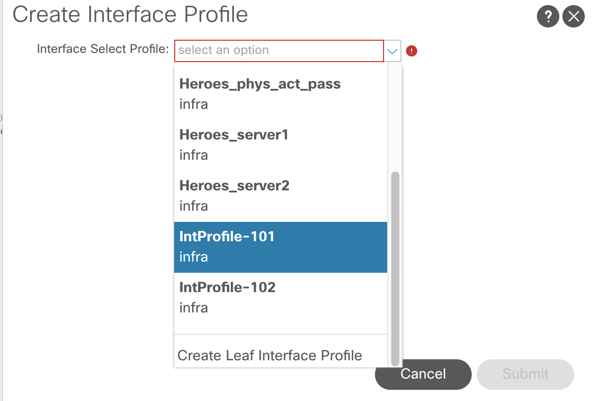
Creating the interface profile has the option to create the interface selector. This is selecting the physical port. As stated previously, it is better to create selectors for all ports individually.
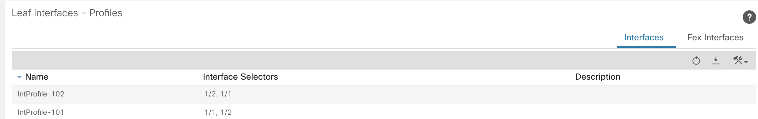
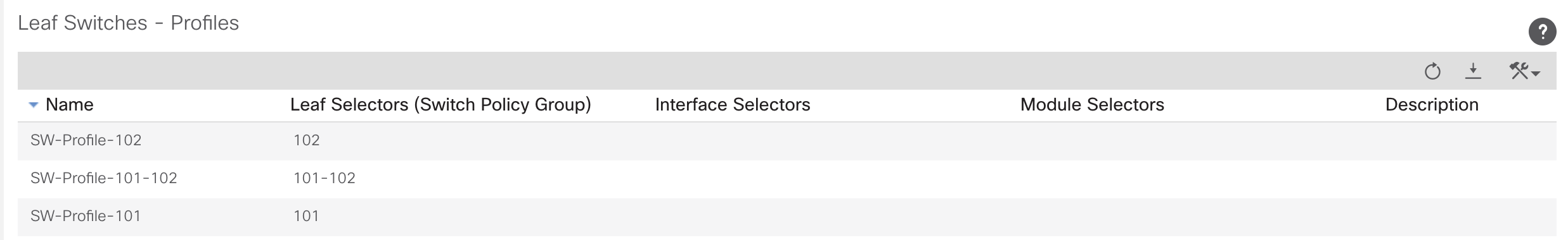
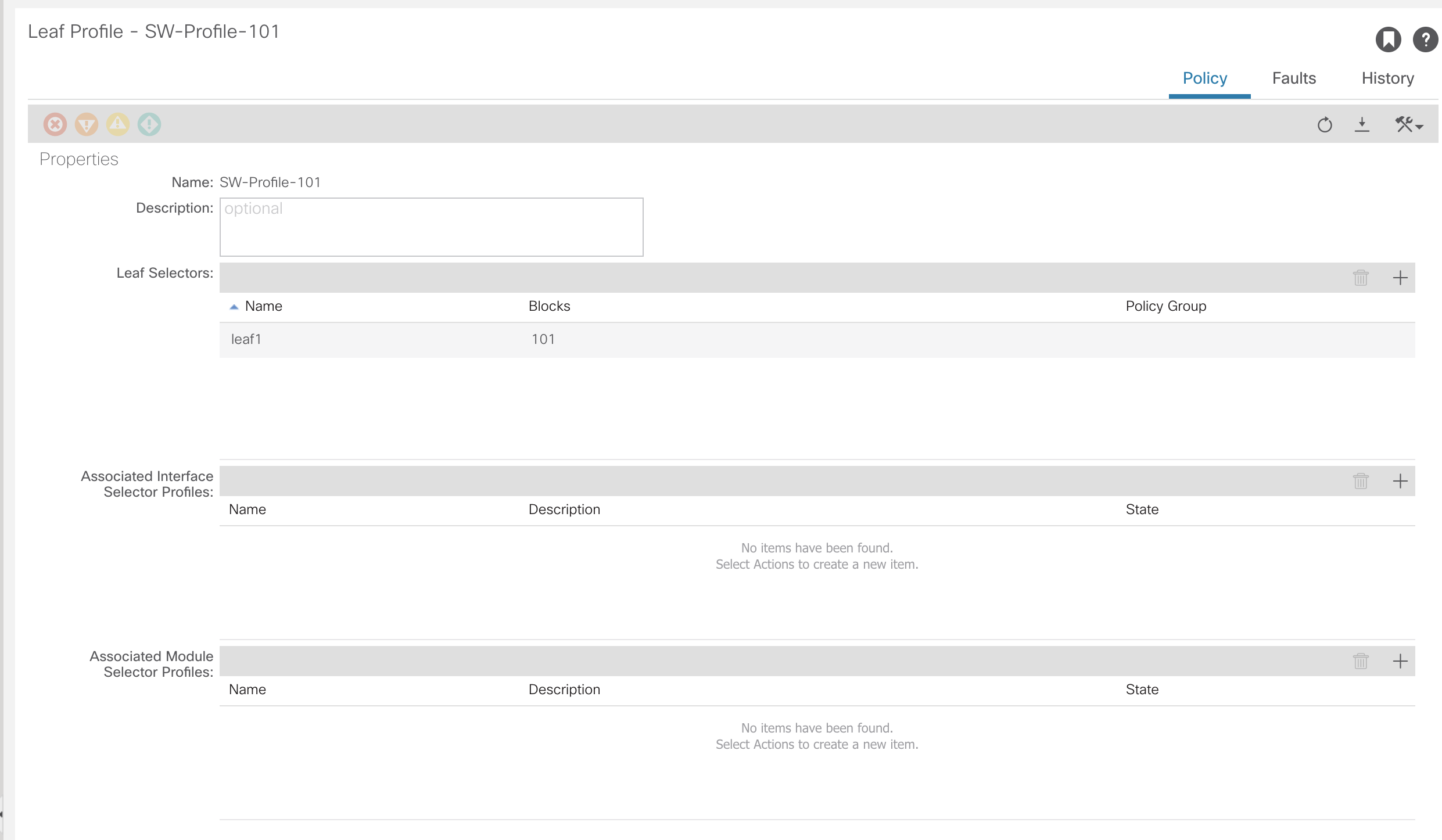
Now the interface selectors and interface profiles have been created, they need to be tied back to the switch profiles created earlier. For this, return to the switch profile under:Fabric >> Access Policies >> Switches >> Leaf Switches >> Profiles >> SW-Profile-101
All that is needed is to select the interface selector profile
What has now been created are the switch profiles and interface profiles with interface selectors attaches, as shown in this diagram.
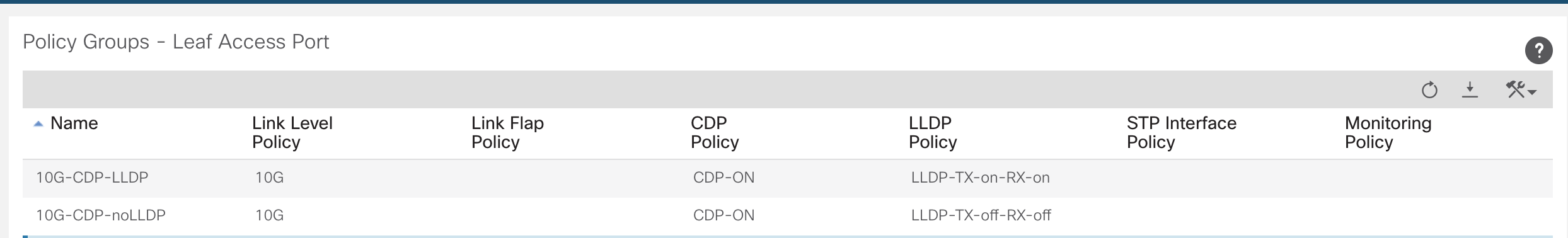
Interface Policy Groups
The interface policy group is where the link between the individual port configuration elements, created under Interface Policies, are applied to a physical switch port on a leaf.
The diagram below is to help with the flow of what is happening. There have been numerous policies created so far, but nothing is actually configuring a physical switch port.
The following has been created;
- Switch Profile – references a physical switch or switches
- Interface Profile – is a container for physical switch ports on the Switch Profile it is referenced by
- Port selectors – these are the physical ports that are contained inside the Interface Profile and then referenced by a switch
This next step is to use the elements created under Interface Policies to have configuration applied to those switch ports.
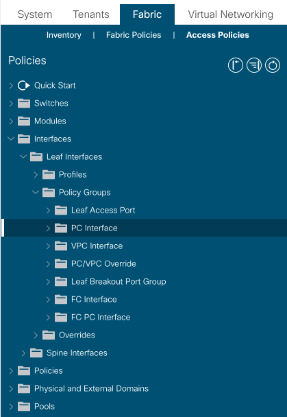
To configure Interface Policy Groups navigate to:Fabric >> Access Policies >> Interfaces >> Leaf/Spine Interfaces >> Policy Groups
At this point there is a choice of type of port policy that can be made such as; access, port channel, virtual port channel, etc.
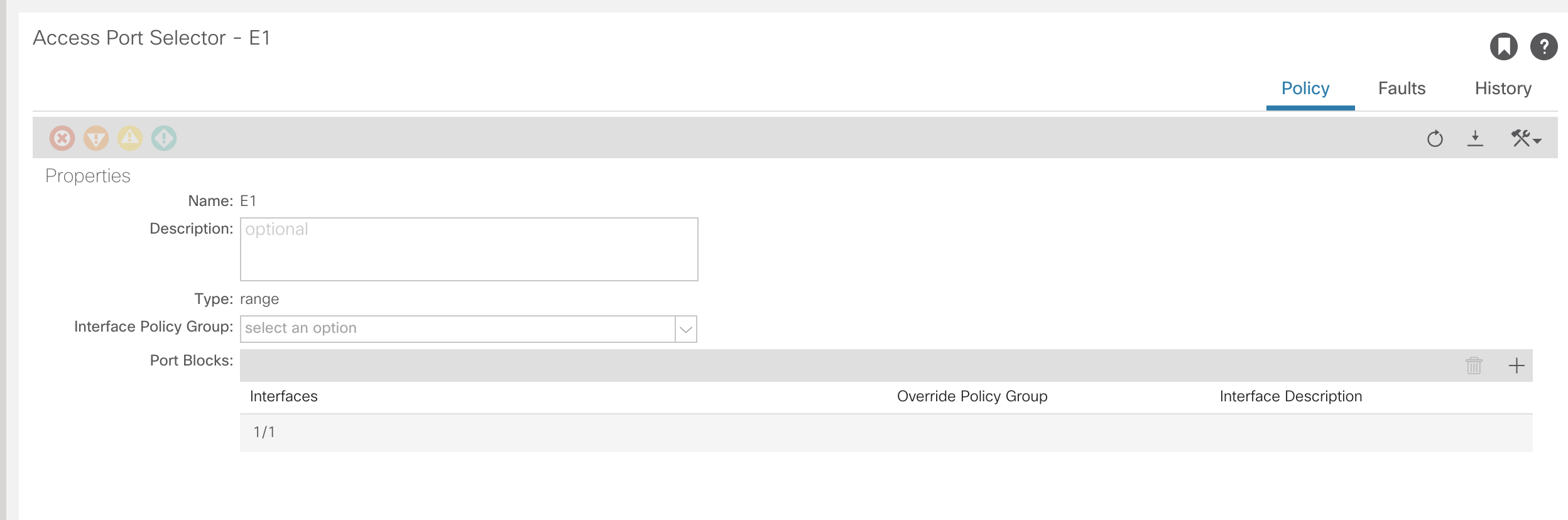
Creating an Access Port Policy
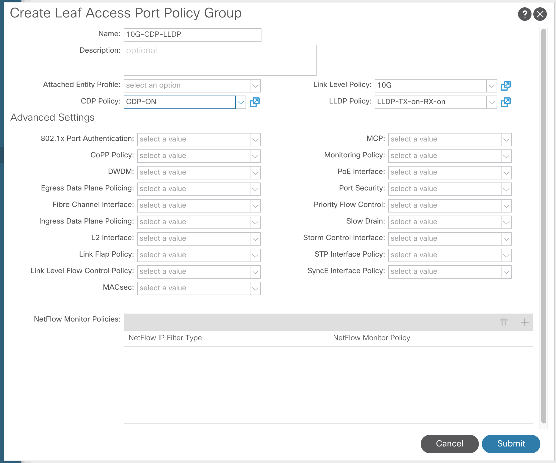
At this stage, no configuration has been applied to any ports. To attach the profile that has just been created to physical ports, navigate to the Interface Policy.Fabric >> Access Policies >> Interfaces >> Leaf/Spine Interfaces >> IntProf-101/102
Go into the specific interface and select the Port Policy to be applied.

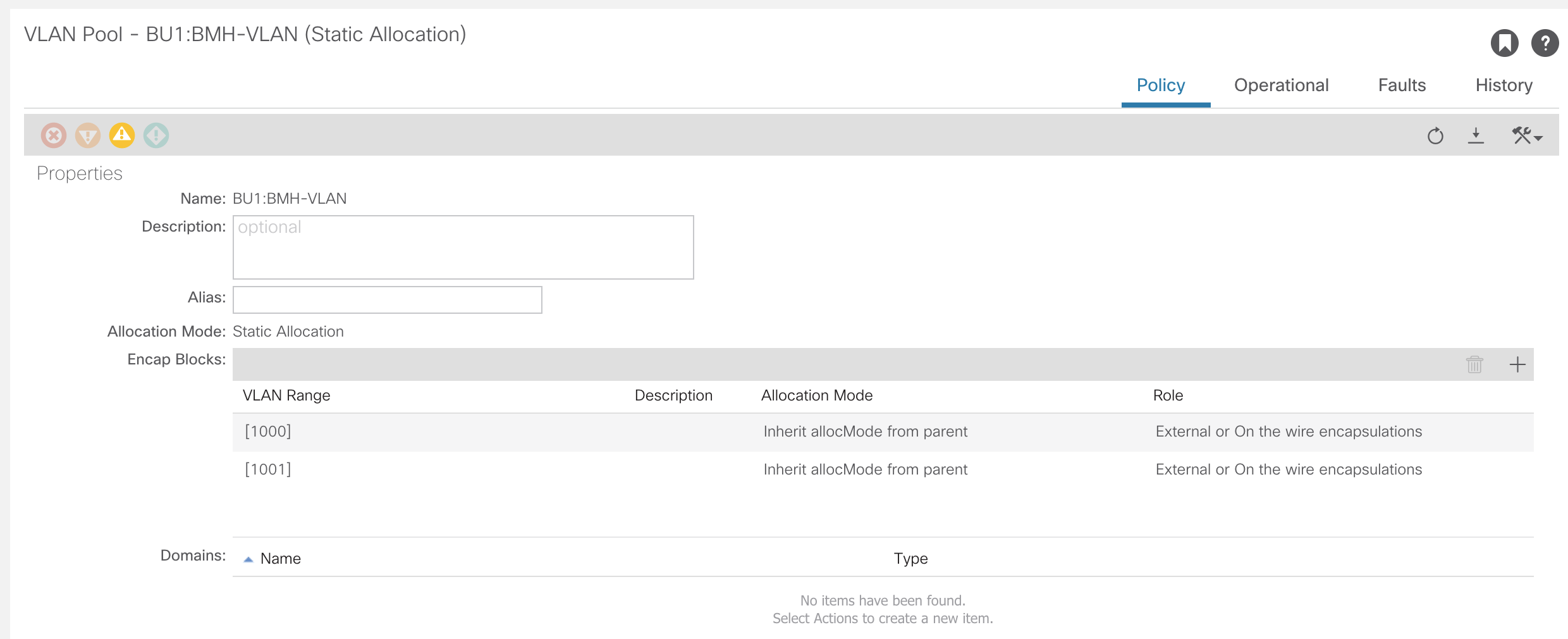
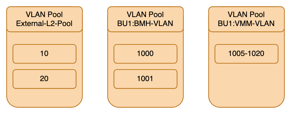
VLAN Pools
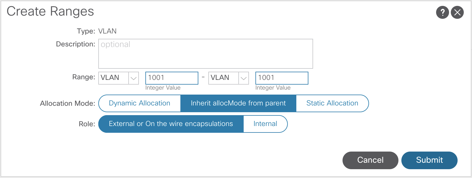
In ACI, VLANs are no longer referring to a specific broadcast domain or a subnet, as they do in traditional networking. However, the VLAN is used as classification inside each leaf switch.
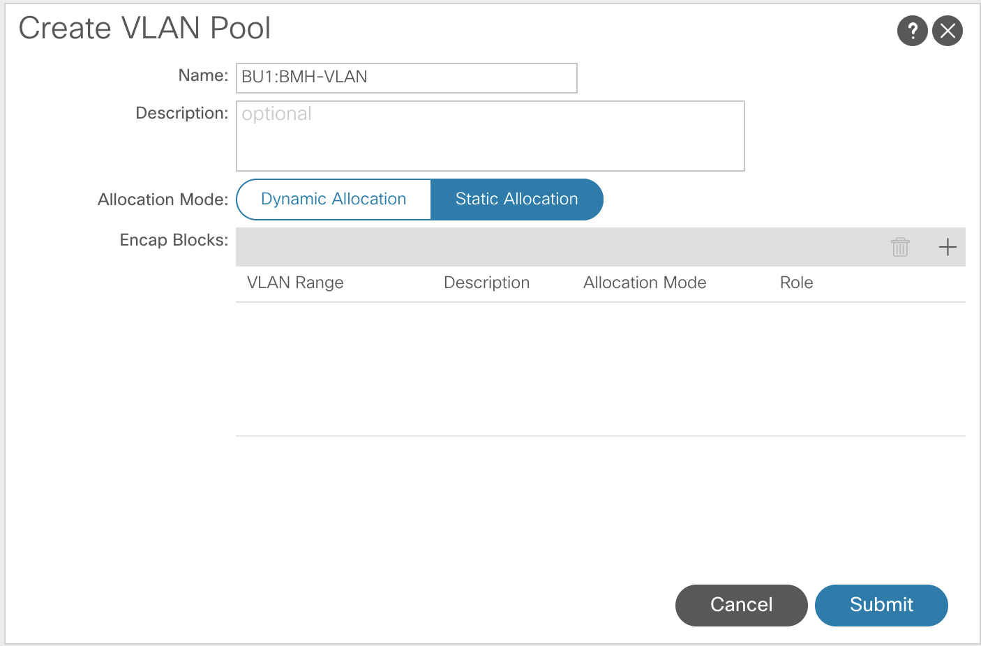
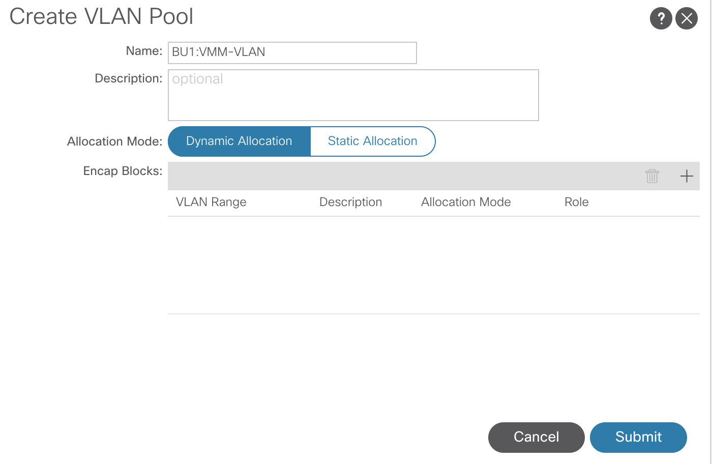
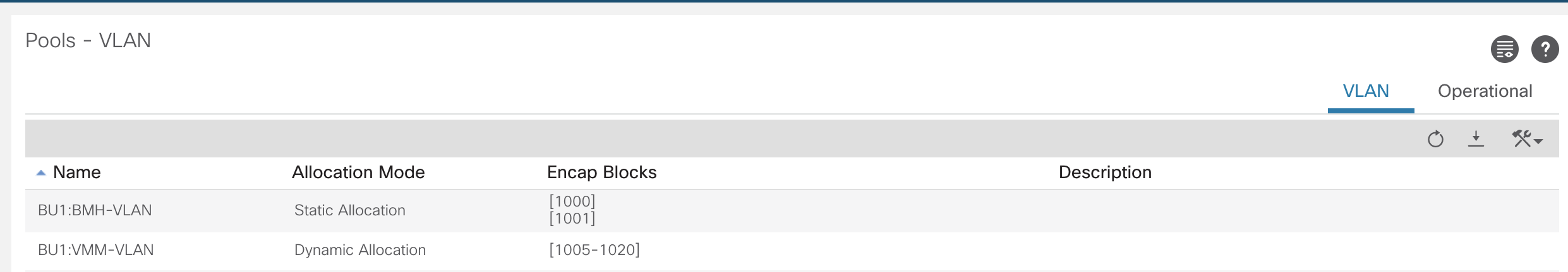
There are two different types of VLAN pools in ACI, dynamic and static.
- Dynamic Pools are for Virtual Machine Manager (VMM) domains such as; Hyper-V, vCenter
- As VMs are created, a VLAN from that pool will be used
- Static Pools are for Bare Metal servers, Appliances, etc
- Static VLANs are manually assigned to endpoints
To configure a VLAN pool, navigate to:Fabric >> Access Policies >> Pools >> VLAN
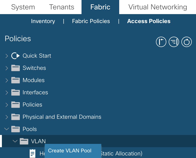
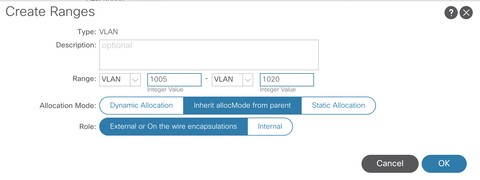
The pools created will eventually map back to the Switch Profiles. Currently, they are not referenced by anything.
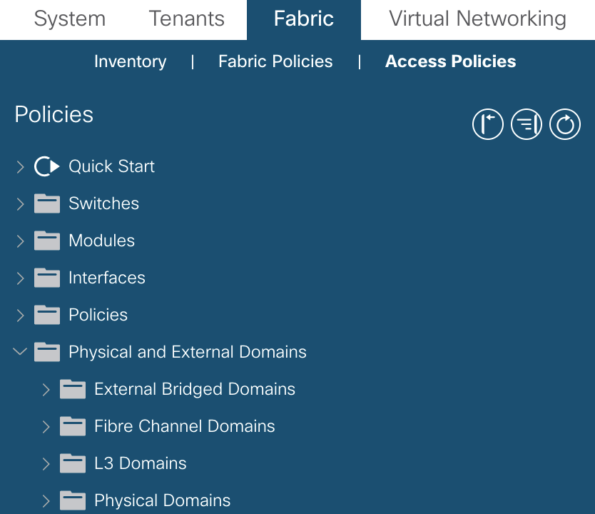
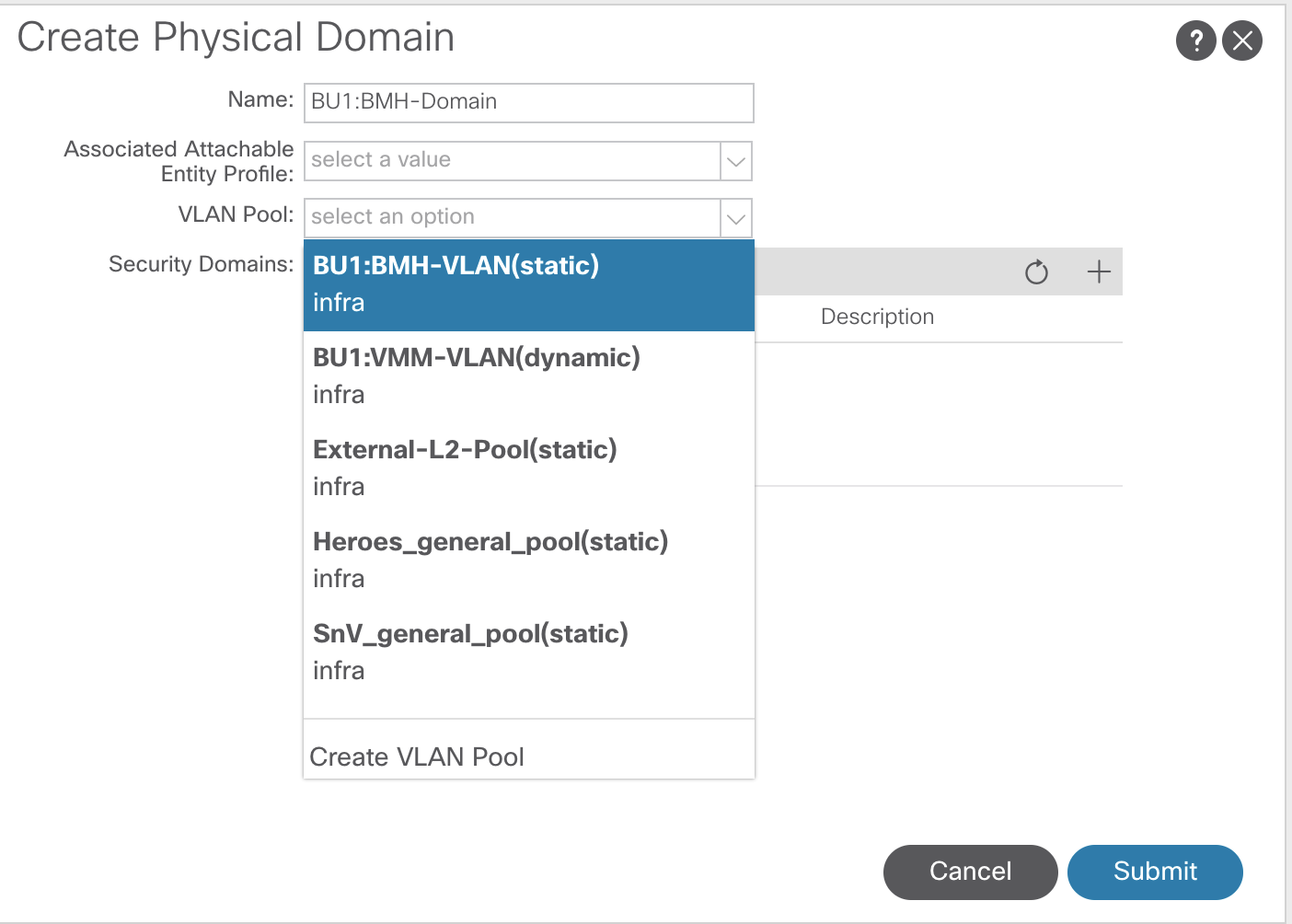
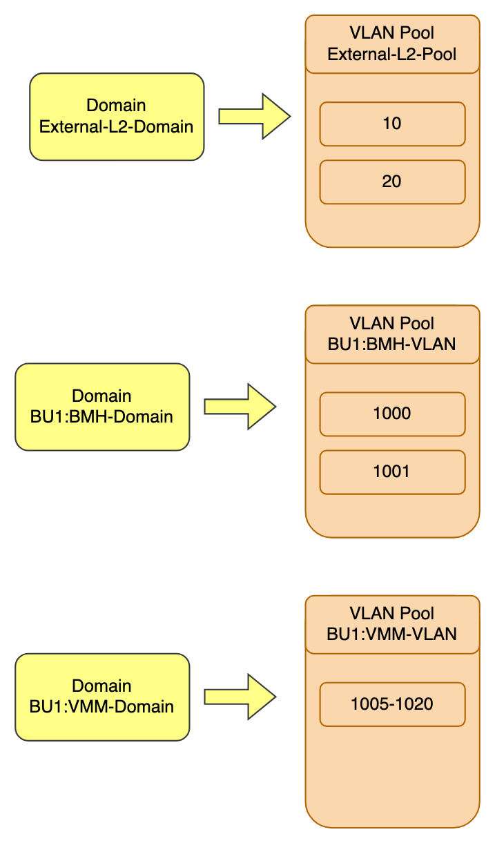
Domains
Endpoint connectivity options. How we are going to connect to the fabric. There are four different domains in ACI.
- Physical
- Physical servers
- VMM
- Hyper-V, vCenter
- L2 External Domains
- Border leafs handing off to a L2 switch for migration into ACI
- L3 External Domains
- Border leaf handing off to routers
Domains are the glue between the configuration performed in the fabric tab to the policy model and EPG configuration under the tenant tab.
To configure the domains, go to:Fabric >> Access Policies >> Physical and External Domains
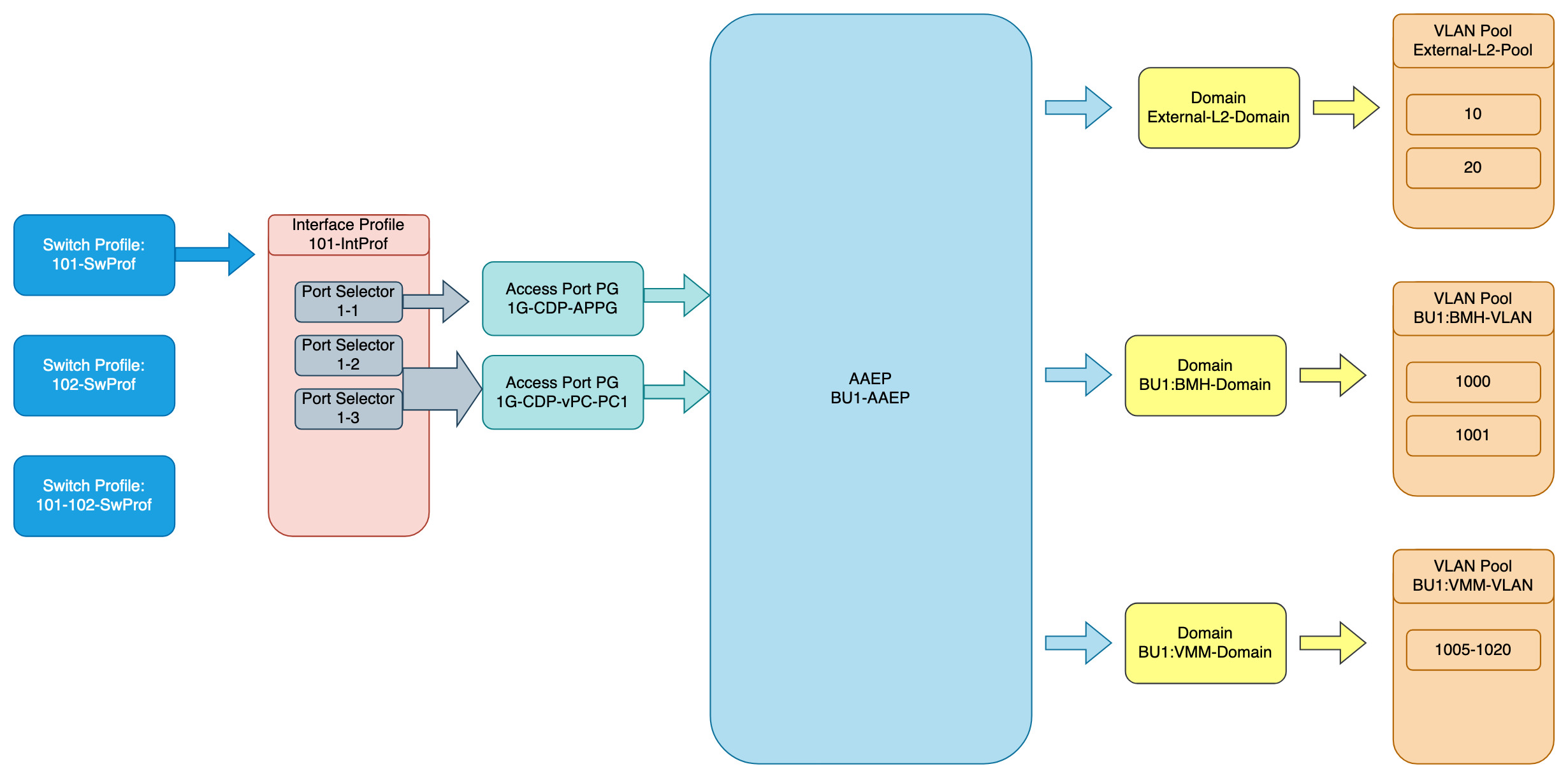
Attachable (Access) Entity Profiles (AAEP or AEP)
This is the component that sits between the VLANs and Domains and the Switch and Interface Policies.
- AAEPs are contained within Interface Policy Groups
- AAEPs contain domains
- Brings together interface and VLANs
- APIC then knows where to deploy the VLANs – which switch/port
- Generally you will have 1 AEP per tenant
- Not a hard rule
- Required to deploy VLAN pools on leafs
- Defines the range, but does not push config until an endpoint is connected
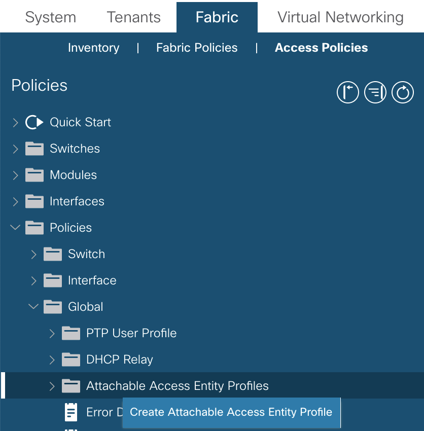
To configure AAEPs navigate to:Fabric >> Access Policies >> Global Policies >> Attachable Access Entity Profiles
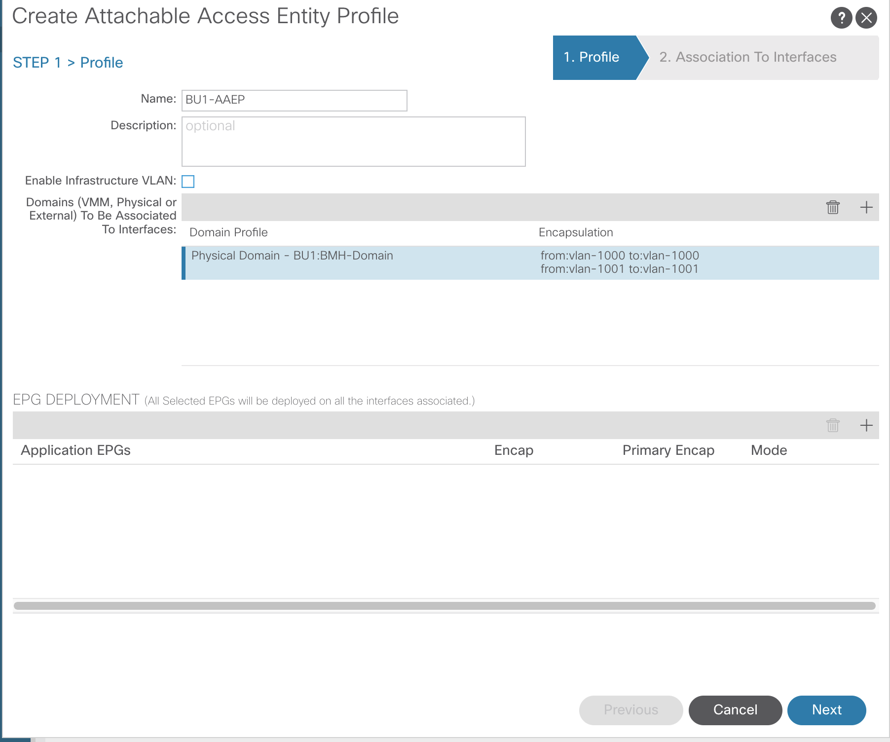
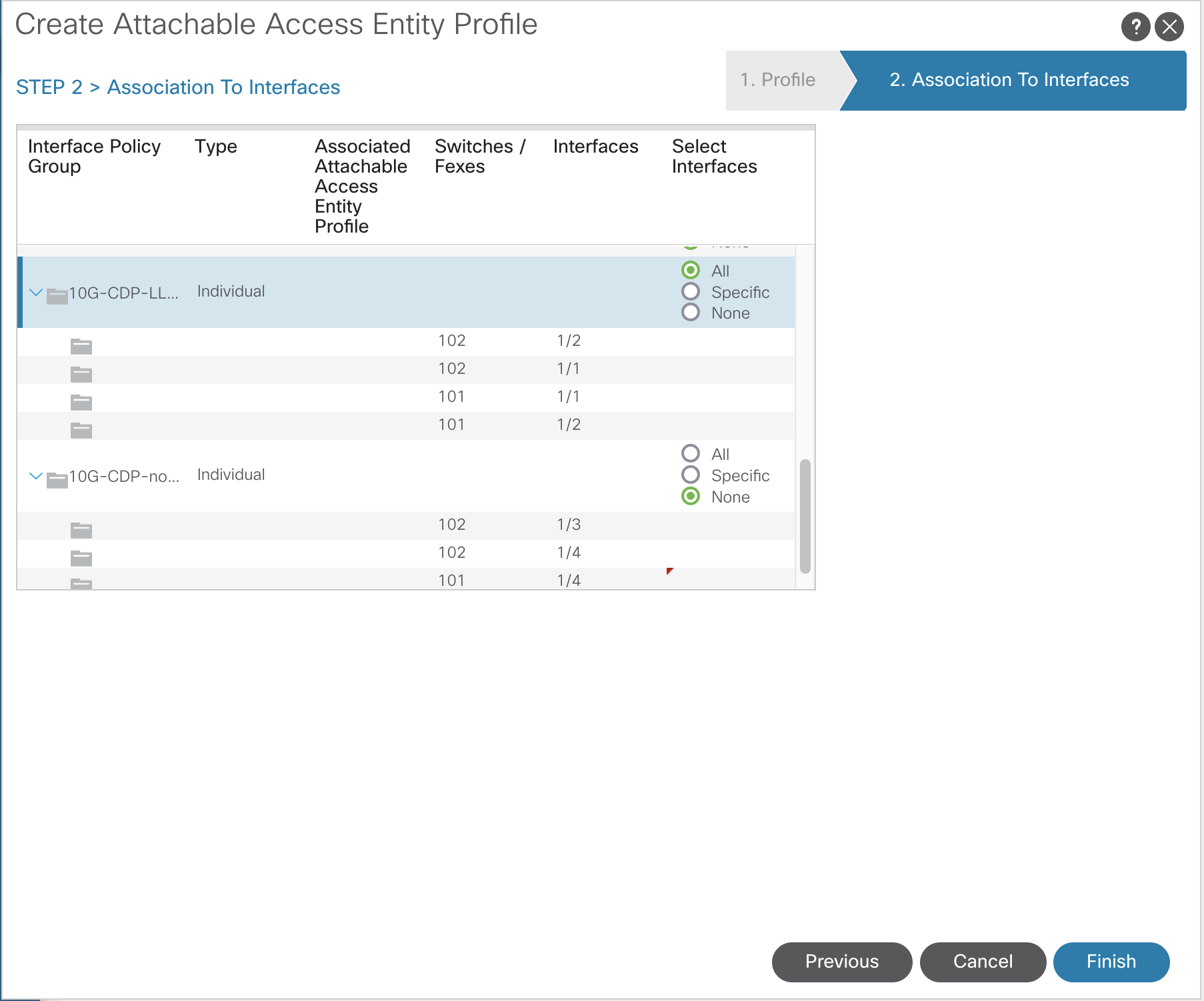
As stated, the AAEP is where VLANs are connected to the physical. The two screenshot below demonstrates the VLANs connected to the domain and the association to the interfaces through the Interface Policy Group.
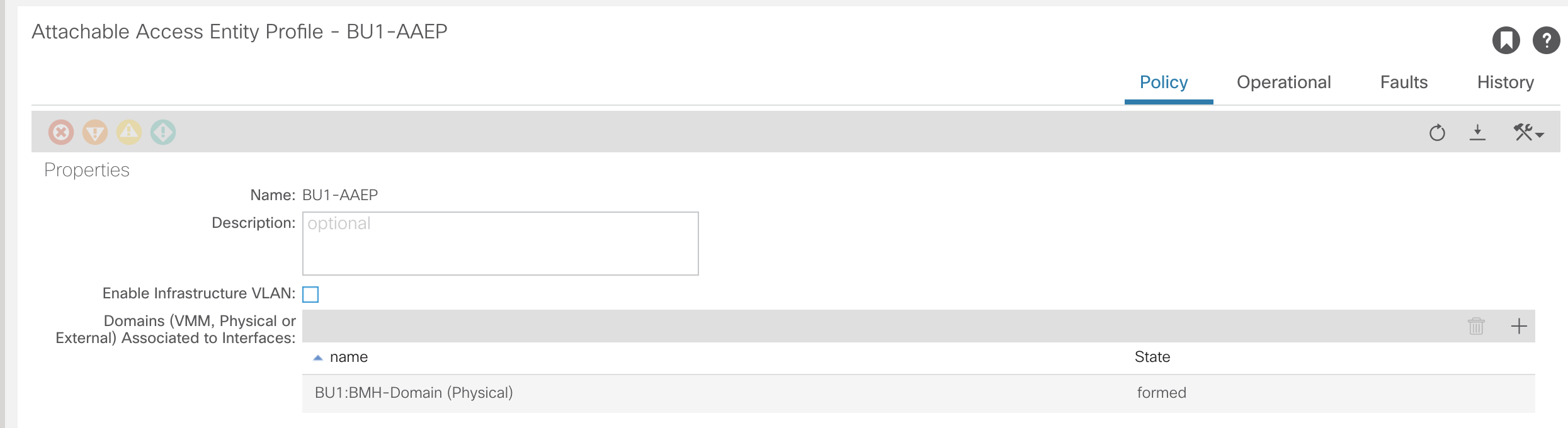
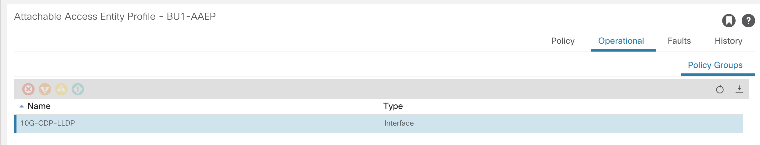
This is now the stage where endpoints can be attached and traffic passed.